Cirkit Designer Logo
Cirkit Designer
Your all-in-one circuit design IDE
Home / 
Component Documentation

How to Use MINIBOOST 5V @ 1A : Examples, Pinouts, and Specs

Image of MINIBOOST 5V @ 1A
Cirkit Designer LogoDesign with MINIBOOST 5V @ 1A in Cirkit Designer

Introduction

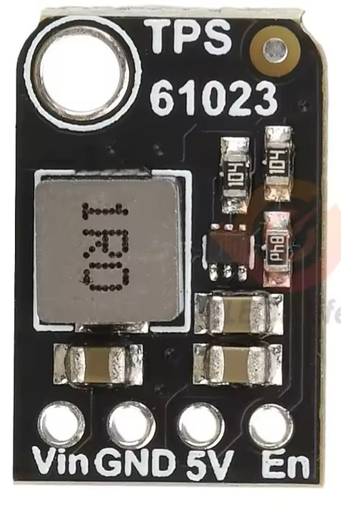
The MINIBOOST 5V @ 1A is a compact DC-DC boost converter module designed and manufactured by Adafruit. It utilizes the TPS61023 IC to efficiently step up input voltages to a stable 5V output, capable of delivering up to 1A of current. This module is ideal for powering small electronic devices, microcontrollers, and low-power peripherals from lower voltage sources such as batteries.

Explore Projects Built with MINIBOOST 5V @ 1A

Use Cirkit Designer to design, explore, and prototype these projects online. Some projects support real-time simulation. Click "Open Project" to start designing instantly!
Battery-Powered Lora G2 Node Station with 18650 Li-ion Batteries and Boost Converter
Image of Custom-Lora-G2-Node: A project utilizing MINIBOOST 5V @ 1A  in a practical application
This circuit is a portable power supply system that uses multiple 18650 Li-ion batteries to provide a stable 5V output through a boost converter. It includes a fast charging module with a USB-C input for recharging the batteries and a battery indicator for monitoring the battery status. The system powers a Lora G2 Node Station, making it suitable for wireless communication applications.
Cirkit Designer LogoOpen Project in Cirkit Designer
Battery-Powered DC Motor Control with USB Charging and LED Indicator
Image of lumantas: A project utilizing MINIBOOST 5V @ 1A  in a practical application
This circuit is designed to charge a Li-ion battery and power a DC motor and a 12V LED. The TP4056 module manages the battery charging process, while the PowerBoost 1000 and MT3608 boost converters step up the voltage to drive the motor and LED, respectively. Two rocker switches control the power flow to the LED and the charging circuit.
Cirkit Designer LogoOpen Project in Cirkit Designer
Battery-Powered Boost Converter with USB Type-C and BMS
Image of Weird Case: A project utilizing MINIBOOST 5V @ 1A  in a practical application
This circuit is a power management and conversion system that includes a boost converter, battery management system (BMS), and various MOSFETs and passive components. It is designed to regulate and boost the voltage from a 2000mAh battery, providing stable power output through a USB Type C interface. The circuit also includes protection and switching mechanisms to ensure safe and efficient power delivery.
Cirkit Designer LogoOpen Project in Cirkit Designer
Wi-Fi Controlled RGB LED Strip with Battery Management System
Image of OpenTimingProject - Basic node: A project utilizing MINIBOOST 5V @ 1A  in a practical application
This circuit features a Wemos D1 Mini microcontroller powered by a 18650 Li-ion battery through a TP4056 charging module, with power control managed by a rocker switch. The Wemos D1 Mini controls a WS2812 RGB LED strip, with the data line connected to the D4 pin and power lines controlled by the switch. Multiple pushbuttons are connected to the D0 pin through a resistor, likely for user input to control the LED strip or other functions in the microcontroller's code.
Cirkit Designer LogoOpen Project in Cirkit Designer

Explore Projects Built with MINIBOOST 5V @ 1A

Use Cirkit Designer to design, explore, and prototype these projects online. Some projects support real-time simulation. Click "Open Project" to start designing instantly!
Image of Custom-Lora-G2-Node: A project utilizing MINIBOOST 5V @ 1A  in a practical application
Battery-Powered Lora G2 Node Station with 18650 Li-ion Batteries and Boost Converter
This circuit is a portable power supply system that uses multiple 18650 Li-ion batteries to provide a stable 5V output through a boost converter. It includes a fast charging module with a USB-C input for recharging the batteries and a battery indicator for monitoring the battery status. The system powers a Lora G2 Node Station, making it suitable for wireless communication applications.
Cirkit Designer LogoOpen Project in Cirkit Designer
Image of lumantas: A project utilizing MINIBOOST 5V @ 1A  in a practical application
Battery-Powered DC Motor Control with USB Charging and LED Indicator
This circuit is designed to charge a Li-ion battery and power a DC motor and a 12V LED. The TP4056 module manages the battery charging process, while the PowerBoost 1000 and MT3608 boost converters step up the voltage to drive the motor and LED, respectively. Two rocker switches control the power flow to the LED and the charging circuit.
Cirkit Designer LogoOpen Project in Cirkit Designer
Image of Weird Case: A project utilizing MINIBOOST 5V @ 1A  in a practical application
Battery-Powered Boost Converter with USB Type-C and BMS
This circuit is a power management and conversion system that includes a boost converter, battery management system (BMS), and various MOSFETs and passive components. It is designed to regulate and boost the voltage from a 2000mAh battery, providing stable power output through a USB Type C interface. The circuit also includes protection and switching mechanisms to ensure safe and efficient power delivery.
Cirkit Designer LogoOpen Project in Cirkit Designer
Image of OpenTimingProject - Basic node: A project utilizing MINIBOOST 5V @ 1A  in a practical application
Wi-Fi Controlled RGB LED Strip with Battery Management System
This circuit features a Wemos D1 Mini microcontroller powered by a 18650 Li-ion battery through a TP4056 charging module, with power control managed by a rocker switch. The Wemos D1 Mini controls a WS2812 RGB LED strip, with the data line connected to the D4 pin and power lines controlled by the switch. Multiple pushbuttons are connected to the D0 pin through a resistor, likely for user input to control the LED strip or other functions in the microcontroller's code.
Cirkit Designer LogoOpen Project in Cirkit Designer

Common Applications and Use Cases

  • Powering 5V microcontrollers (e.g., Arduino, ESP32) from 3.7V LiPo batteries
  • Boosting voltage from AA/AAA battery packs
  • Portable electronics and wearables
  • Low-power IoT devices
  • Backup power systems

Technical Specifications

The following table outlines the key technical details of the MINIBOOST 5V @ 1A module:

Parameter Value
Input Voltage Range 1.8V to 5.5V
Output Voltage 5V (regulated)
Maximum Output Current 1A
Efficiency Up to 90% (depending on load)
Switching Frequency 1.5 MHz
Dimensions 11.5mm x 17.5mm x 4mm
Weight ~1g

Pin Configuration and Descriptions

The MINIBOOST module has four pins, as described in the table below:

Pin Name Description
VIN Input voltage pin. Connect to a power source (e.g., battery) within 1.8V-5.5V.
GND Ground pin. Connect to the ground of your circuit.
VOUT Regulated 5V output pin. Connect to the load or device requiring 5V power.
EN Enable pin. Pull high to enable the module, or low to disable it.

Usage Instructions

How to Use the Component in a Circuit

  1. Connect the Input Voltage (VIN):

    • Attach a power source (e.g., a 3.7V LiPo battery or a 2xAA battery pack) to the VIN pin.
    • Ensure the input voltage is within the range of 1.8V to 5.5V.
  2. Connect the Ground (GND):

    • Connect the GND pin to the ground of your circuit.
  3. Connect the Output Voltage (VOUT):

    • Attach the device or load requiring 5V power to the VOUT pin.
    • Ensure the load does not exceed the maximum output current of 1A.
  4. Enable the Module:

    • Pull the EN pin high (connect to VIN) to enable the module.
    • To disable the module, pull the EN pin low (connect to GND).

Important Considerations and Best Practices

  • Input Voltage Range: Ensure the input voltage remains within the specified range (1.8V to 5.5V). Exceeding this range may damage the module.
  • Output Current Limit: Do not exceed the maximum output current of 1A to prevent overheating or damage.
  • Heat Dissipation: Although the module is efficient, it may generate heat under high loads. Ensure adequate ventilation or heat dissipation if operating near the maximum current.
  • Decoupling Capacitors: For optimal performance, use decoupling capacitors (e.g., 10µF) close to the input and output pins to reduce noise and improve stability.

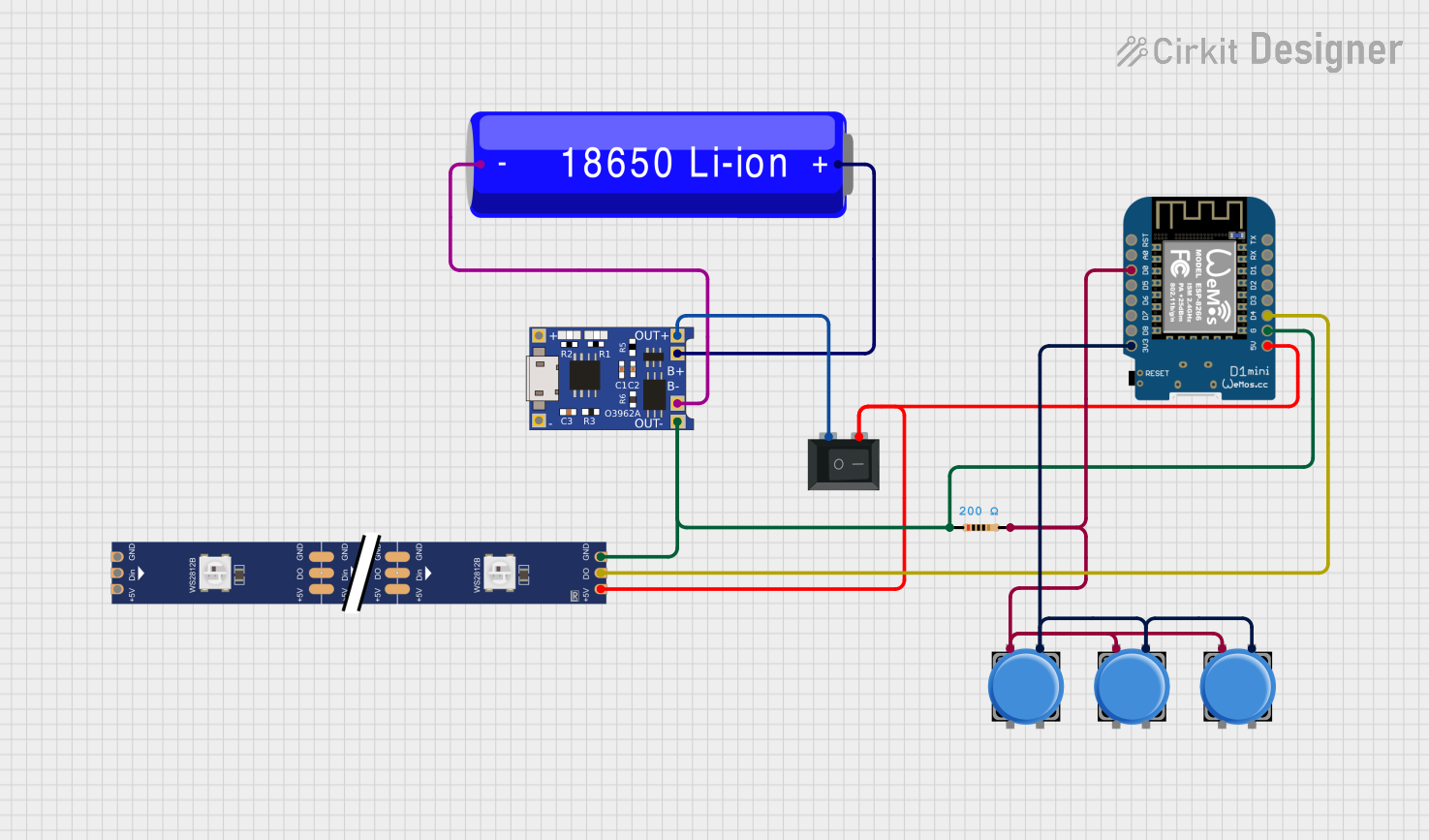
Example: Using MINIBOOST with Arduino UNO

The following example demonstrates how to power an Arduino UNO using the MINIBOOST module and a 3.7V LiPo battery.

Circuit Connections

  1. Connect the positive terminal of the LiPo battery to the VIN pin of the MINIBOOST.
  2. Connect the negative terminal of the LiPo battery to the GND pin of the MINIBOOST.
  3. Connect the VOUT pin of the MINIBOOST to the 5V pin of the Arduino UNO.
  4. Connect the GND pin of the MINIBOOST to the GND pin of the Arduino UNO.

Arduino Code Example

// Example code to blink an LED on pin 13 of Arduino UNO
// This demonstrates the Arduino running on power supplied by the MINIBOOST module.

void setup() {
  pinMode(13, OUTPUT); // Set pin 13 as an output
}

void loop() {
  digitalWrite(13, HIGH); // Turn the LED on
  delay(1000);            // Wait for 1 second
  digitalWrite(13, LOW);  // Turn the LED off
  delay(1000);            // Wait for 1 second
}

Troubleshooting and FAQs

Common Issues and Solutions

  1. No Output Voltage:

    • Cause: The EN pin is not pulled high.
    • Solution: Ensure the EN pin is connected to VIN to enable the module.
  2. Output Voltage Drops Under Load:

    • Cause: The load exceeds the maximum output current of 1A.
    • Solution: Reduce the load or ensure the connected device does not draw more than 1A.
  3. Module Overheating:

    • Cause: Prolonged operation at high current or insufficient ventilation.
    • Solution: Reduce the load or improve heat dissipation by adding airflow or a heatsink.
  4. Noise or Instability in Output Voltage:

    • Cause: Insufficient decoupling capacitors.
    • Solution: Add a 10µF capacitor close to the VOUT pin to stabilize the output.

FAQs

Q: Can I use the MINIBOOST to power a Raspberry Pi?
A: The MINIBOOST is not recommended for powering a Raspberry Pi, as it typically requires more than 1A of current under load.

Q: What happens if the input voltage drops below 1.8V?
A: The module will stop boosting and the output voltage will drop. Ensure the input voltage remains within the specified range.

Q: Can I leave the EN pin floating?
A: No, the EN pin must be explicitly pulled high to enable the module or low to disable it. Leaving it floating may result in unpredictable behavior.