How to Use MAX31856: Examples, Pinouts, and Specs
Introduction
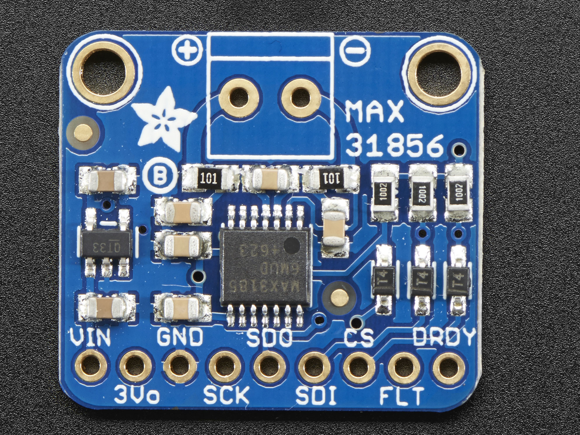
The MAX31856, manufactured by Maxim Integrated, is a high-precision thermocouple-to-digital converter designed for accurate temperature measurement applications. It supports a wide range of thermocouple types, including K, J, N, R, S, T, E, and B, making it versatile for various industrial and scientific applications. The device features integrated cold-junction compensation, digital filtering, and communicates via an SPI interface, ensuring reliable and precise temperature readings.
Explore Projects Built with MAX31856


Explore Projects Built with MAX31856
Common Applications
- Industrial temperature monitoring and control
- Scientific research and laboratory equipment
- HVAC systems
- Food processing and storage
- Automotive and aerospace temperature sensing
Technical Specifications
Key Technical Details
| Parameter | Value |
|---|---|
| Supply Voltage (VDD) | 3.0V to 3.6V |
| Operating Current | 600µA (typical) |
| Thermocouple Types Supported | K, J, N, R, S, T, E, B |
| Temperature Measurement Range | Dependent on thermocouple type (e.g., -200°C to +1800°C for Type K) |
| Cold-Junction Compensation | Integrated |
| Communication Interface | SPI (Serial Peripheral Interface) |
| Resolution | 19-bit |
| Fault Detection | Open thermocouple, over/under voltage, etc. |
| Operating Temperature Range | -40°C to +125°C |
Pin Configuration and Descriptions
The MAX31856 is available in a 10-pin TDFN package. Below is the pinout and description:
| Pin Number | Pin Name | Description |
|---|---|---|
| 1 | VDD | Power supply input (3.0V to 3.6V). |
| 2 | GND | Ground connection. |
| 3 | CS | Chip Select (active low) for SPI communication. |
| 4 | SCK | Serial Clock input for SPI. |
| 5 | SDI | Serial Data Input for SPI. |
| 6 | SDO | Serial Data Output for SPI. |
| 7 | T+ | Positive thermocouple input. |
| 8 | T- | Negative thermocouple input. |
| 9 | NC | No connection (leave unconnected). |
| 10 | NC | No connection (leave unconnected). |
Usage Instructions
How to Use the MAX31856 in a Circuit
- Power Supply: Connect the VDD pin to a 3.3V power source and the GND pin to ground.
- Thermocouple Connection: Attach the positive lead of the thermocouple to the T+ pin and the negative lead to the T- pin.
- SPI Communication: Connect the CS, SCK, SDI, and SDO pins to the corresponding SPI pins on your microcontroller.
- Bypass Capacitor: Place a 0.1µF ceramic capacitor close to the VDD and GND pins for power supply decoupling.
- Pull-Up Resistors: Use pull-up resistors on the SPI lines if required by your microcontroller.
Important Considerations and Best Practices
- Ensure the thermocouple leads are properly connected to avoid polarity issues.
- Use shielded cables for the thermocouple to minimize noise interference.
- Avoid placing the MAX31856 near high-frequency switching components to reduce EMI.
- Calibrate the system if high accuracy is required for your application.
Example Code for Arduino UNO
Below is an example of how to interface the MAX31856 with an Arduino UNO using the SPI library:
#include <SPI.h>

// Define MAX31856 SPI pins
#define CS_PIN 10  // Chip Select pin

// MAX31856 Registers
#define REG_CR0 0x00  // Configuration Register 0
#define REG_CR1 0x01  // Configuration Register 1
#define REG_LTCBH 0x0C // High byte of temperature data

void setup() {
  // Initialize Serial Monitor
  Serial.begin(9600);

  // Initialize SPI
  SPI.begin();
  pinMode(CS_PIN, OUTPUT);
  digitalWrite(CS_PIN, HIGH); // Set CS high to start

  // Configure MAX31856
  writeRegister(REG_CR0, 0x80); // Enable conversion mode
  writeRegister(REG_CR1, 0x03); // Set thermocouple type (e.g., Type K)
}

void loop() {
  // Read temperature data
  int16_t tempData = readTemperature();
  float temperature = tempData * 0.0078125; // Convert to Celsius

  // Print temperature to Serial Monitor
  Serial.print("Temperature: ");
  Serial.print(temperature);
  Serial.println(" °C");

  delay(1000); // Wait 1 second before next reading
}

// Function to write to a MAX31856 register
void writeRegister(uint8_t reg, uint8_t value) {
  digitalWrite(CS_PIN, LOW); // Select the MAX31856
  SPI.transfer(reg | 0x80);  // Set MSB to 1 for write operation
  SPI.transfer(value);       // Write the value
  digitalWrite(CS_PIN, HIGH); // Deselect the MAX31856
}

// Function to read temperature data
int16_t readTemperature() {
  digitalWrite(CS_PIN, LOW); // Select the MAX31856
  SPI.transfer(REG_LTCBH & 0x7F); // Set MSB to 0 for read operation
  uint8_t msb = SPI.transfer(0x00); // Read high byte
  uint8_t lsb = SPI.transfer(0x00); // Read low byte
  digitalWrite(CS_PIN, HIGH); // Deselect the MAX31856

  return (msb << 8) | lsb; // Combine high and low bytes
}
Troubleshooting and FAQs
Common Issues and Solutions
No Temperature Reading:
- Ensure the thermocouple is properly connected to the T+ and T- pins.
- Verify that the SPI connections are correct and secure.
- Check the power supply voltage (3.3V) and ensure it is stable.
Incorrect Temperature Values:
- Confirm the thermocouple type is correctly configured in the MAX31856 registers.
- Check for noise or interference on the thermocouple leads.
- Verify the cold-junction compensation is functioning properly.
SPI Communication Fails:
- Ensure the CS, SCK, SDI, and SDO pins are correctly connected to the microcontroller.
- Verify the SPI clock speed is within the MAX31856's supported range.
FAQs
Q: Can the MAX31856 measure multiple thermocouples simultaneously?
A: No, the MAX31856 is designed to interface with a single thermocouple at a time. For multiple thermocouples, you will need multiple MAX31856 devices or a multiplexer.
Q: What is the accuracy of the MAX31856?
A: The accuracy depends on the thermocouple type and temperature range. For example, with a Type K thermocouple, the accuracy is typically ±0.15% of the reading.
Q: Can I use the MAX31856 with a 5V microcontroller?
A: Yes, but you will need level shifters to interface the 3.3V MAX31856 with the 5V logic of the microcontroller.