The Pololu Distance Sensor with Pulse Width Output (Manufacturer Part ID: 4079) is a high-performance distance measuring sensor designed for applications requiring accurate distance readings up to 300 cm. This sensor uses pulse width modulation (PWM) to output distance measurements, making it easy to interface with microcontrollers and other digital systems. Its compact size and reliable performance make it ideal for robotics, automation, and object detection systems.
Explore Projects Built with Pololu Distance Sensor with Pulse Width Output, 300cm Max
Use Cirkit Designer to design, explore, and prototype these projects online. Some projects support real-time simulation. Click "Open Project" to start designing instantly!
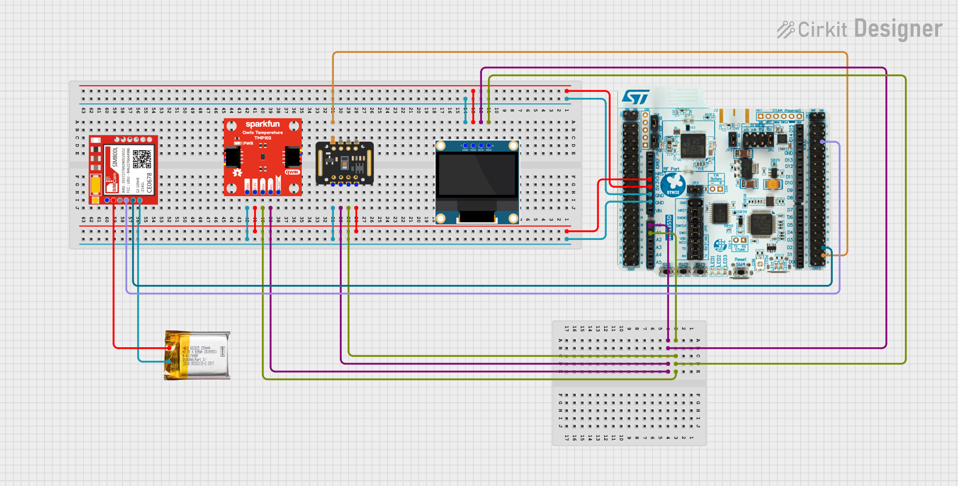
This circuit is a multi-sensor data acquisition system that uses a Nucleo WB55RG microcontroller to interface with a digital temperature sensor (TMP102), a pulse oximeter and heart-rate sensor (MAX30102), and a 0.96" OLED display via I2C. Additionally, it includes a Sim800l module for GSM communication, powered by a 3.7V LiPo battery.
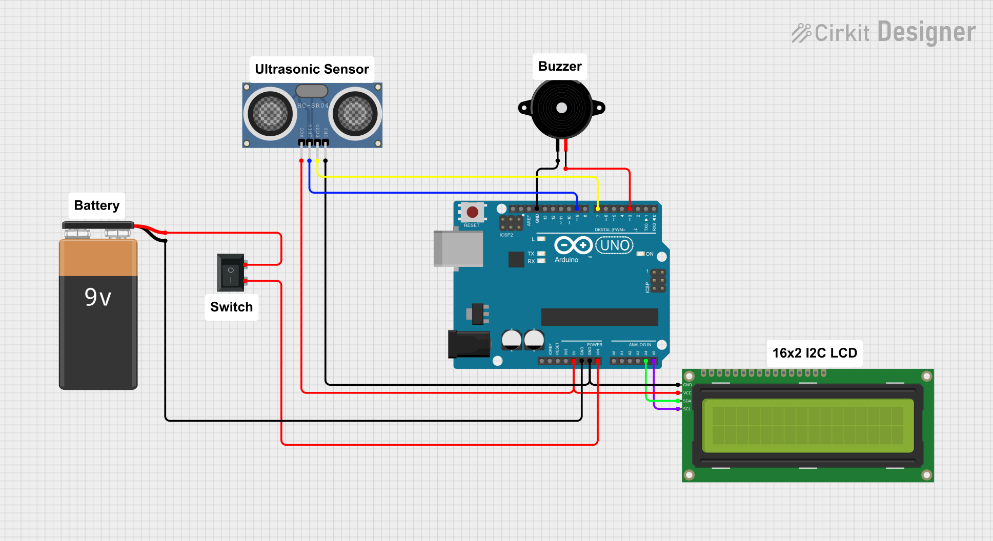
This circuit uses an Arduino UNO to measure the distance of objects using an HC-SR04 ultrasonic sensor and displays the distance on a 16x2 I2C LCD. If an object is detected within 10 cm, a piezo speaker emits a warning sound.
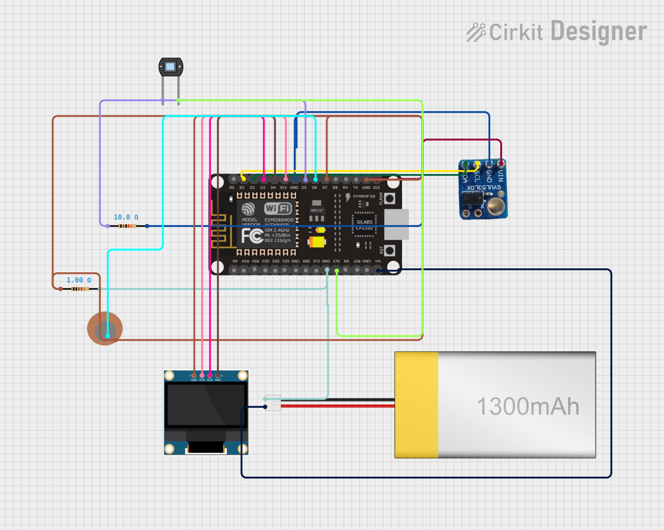
This circuit features an ESP8266 NodeMCU microcontroller interfaced with a VL53L0X time-of-flight distance sensor, a 0.96" OLED display, a piezo sensor, and a photodiode for light detection. The ESP8266 collects data from the sensors, displays readings on the OLED, and hosts a web server to present the information. It is likely designed for distance measurement, light intensity detection, and pressure sensing, with the capability to monitor and display these parameters in real-time over WiFi.
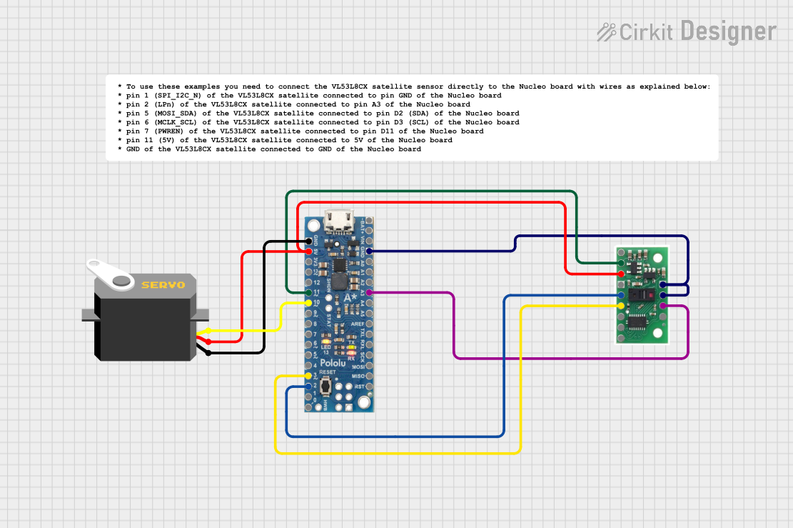
This circuit features an A-Star 32U4 Mini microcontroller connected to a VL53L8CX Time-of-Flight distance sensor and a servo motor. The microcontroller powers both the sensor and the servo, and it is configured to communicate with the sensor via I2C (using pins 2 and 3 for SDA and SCL, respectively) and to control the servo via a PWM signal on pin 10. The purpose of the circuit is likely to measure distances and respond with movements of the servo based on the sensor readings.
Power supply input (4.5 V to 5.5 V). Connect to the 5V pin of your system.
2
GND
Ground. Connect to the ground of your system.
3
PWM OUT
Pulse width output. Provides distance measurement as a PWM signal.
Usage Instructions
How to Use the Component in a Circuit
Power the Sensor: Connect the VIN pin to a 5V power source and the GND pin to the ground of your circuit.
Read the PWM Output: Connect the PWM OUT pin to a digital input pin of your microcontroller. The pulse width of the signal corresponds to the measured distance.
Convert Pulse Width to Distance: Measure the duration of the high pulse on the PWM OUT pin. Use the formula below to calculate the distance:
[
\text{Distance (cm)} = \text{Pulse Width (ms)} \times 10
]
For example, a pulse width of 15 ms corresponds to a distance of 150 cm.
Important Considerations and Best Practices
Power Supply: Ensure a stable 5V power supply to avoid inaccurate readings.
Interference: Avoid placing the sensor near reflective surfaces or strong light sources, as these may affect accuracy.
Mounting: Position the sensor so that it has a clear line of sight to the target object.
Signal Filtering: If the PWM signal is noisy, consider adding a capacitor between the PWM OUT pin and ground to stabilize the output.
Example Code for Arduino UNO
The following Arduino code demonstrates how to read the PWM output from the sensor and calculate the distance:
// Define the pin connected to the PWM OUT of the sensor
const int pwmPin = 2;

void setup() {
  // Initialize serial communication for debugging
  Serial.begin(9600);

  // Set the PWM pin as an input
  pinMode(pwmPin, INPUT);
}

void loop() {
  // Measure the duration of the HIGH pulse on the PWM pin
  unsigned long pulseWidth = pulseIn(pwmPin, HIGH);

  // Convert the pulse width to distance in cm
  float distance = pulseWidth * 0.1; // 1 ms = 10 cm

  // Print the distance to the Serial Monitor
  Serial.print("Distance: ");
  Serial.print(distance);
  Serial.println(" cm");

  // Add a small delay for stability
  delay(100);
}
Troubleshooting and FAQs
Common Issues and Solutions
No Output Signal
Cause: The sensor is not powered correctly.
Solution: Verify that the VIN pin is connected to a 5V power source and the GND pin is connected to ground.
Inaccurate Distance Readings
Cause: Interference from reflective surfaces or strong light sources.
Solution: Reposition the sensor to avoid interference and ensure a clear line of sight to the target.
PWM Signal is Unstable
Cause: Electrical noise in the circuit.
Solution: Add a decoupling capacitor (e.g., 0.1 µF) between the PWM OUT pin and ground.
Distance Readings are Stuck at Maximum or Minimum
Cause: The target object is out of the sensor's range.
Solution: Ensure the object is within the 5 cm to 300 cm range.
FAQs
Q: Can this sensor detect transparent objects?
A: The sensor may have difficulty detecting transparent or highly reflective objects. For best results, use opaque and matte surfaces.
Q: How fast can the sensor update distance readings?
A: The sensor provides a new distance reading approximately every 50 ms.
Q: Can I use this sensor with a 3.3V microcontroller?
A: The sensor requires a 5V power supply, but the PWM output can be read by 3.3V logic microcontrollers. Use a level shifter if needed.
Q: What is the accuracy of the sensor?
A: The sensor provides reliable readings with an accuracy of ±5% under ideal conditions.


 Open Project in Cirkit Designer