How to Use HY-SRF05: Examples, Pinouts, and Specs
Introduction
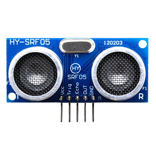
The HY-SRF05 is an ultrasonic distance sensor manufactured by Raspberry Pi 4, with the part ID "Ultrasonic distance sensor." This sensor uses sonar technology to measure the distance to an object by emitting ultrasonic waves and calculating the time taken for the echo to return. It is widely used in robotics, automation, and obstacle detection systems due to its accuracy and ease of use.
Explore Projects Built with HY-SRF05
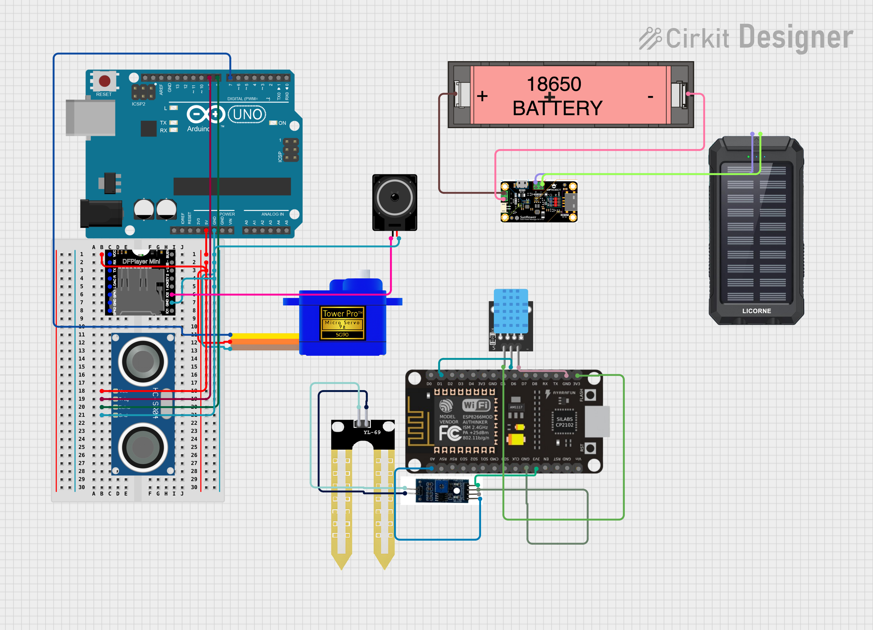
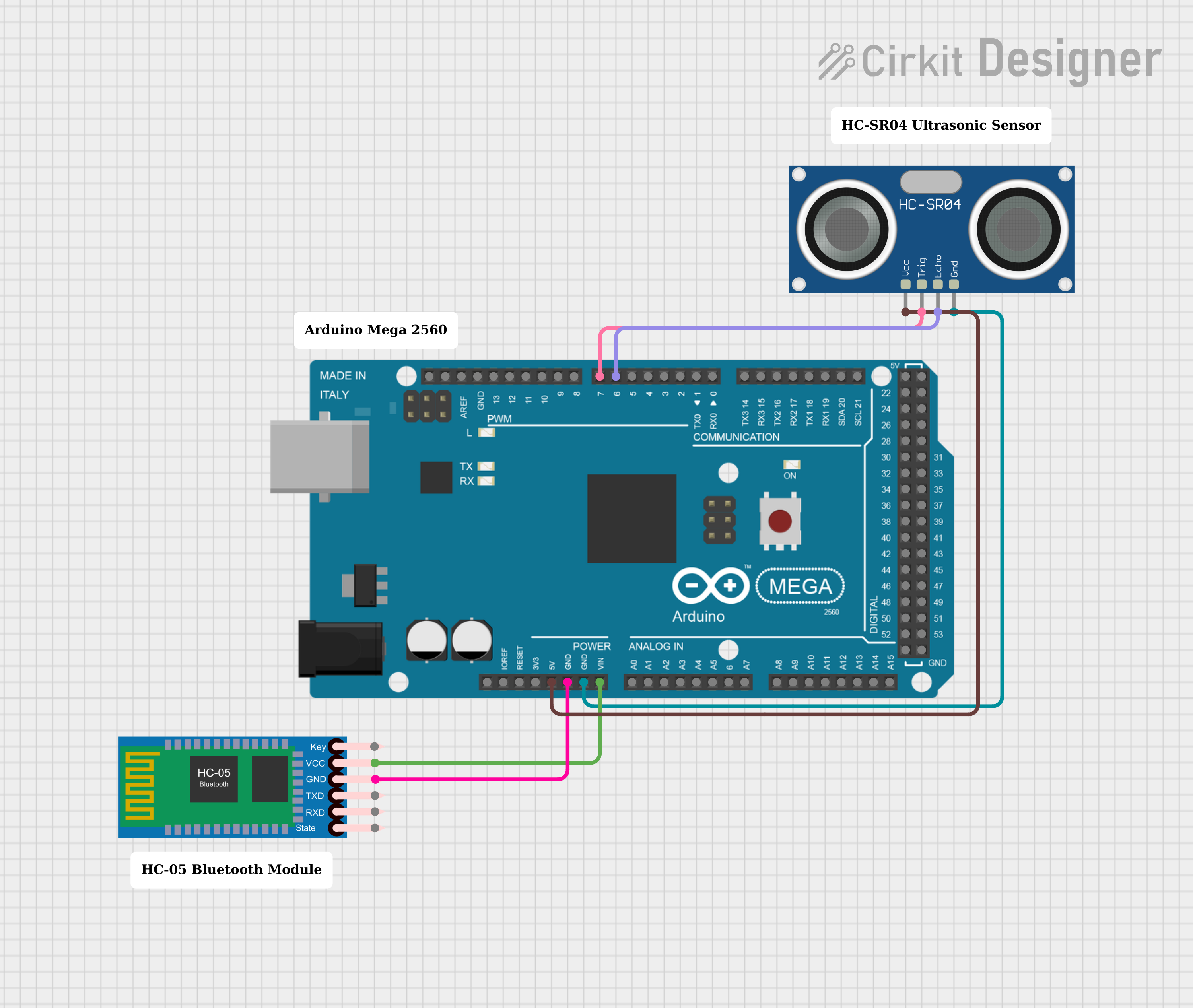


Explore Projects Built with HY-SRF05
Common Applications and Use Cases
- Obstacle detection in robotics
- Distance measurement in automation systems
- Parking assistance systems
- Object tracking and proximity sensing
- Smart home applications, such as automatic doors or lighting systems
Technical Specifications
The HY-SRF05 is designed to provide reliable and accurate distance measurements. Below are its key technical details:
| Parameter | Value |
|---|---|
| Operating Voltage | 5V DC |
| Operating Current | 15 mA (typical) |
| Measuring Range | 2 cm to 4 m |
| Accuracy | ±3 mm |
| Operating Frequency | 40 kHz |
| Trigger Input Signal | 10 µs TTL pulse |
| Echo Output Signal | Pulse width proportional to distance |
| Dimensions | 45 mm x 20 mm x 15 mm |
Pin Configuration and Descriptions
The HY-SRF05 has a 5-pin interface for easy integration into circuits. Below is the pinout:
| Pin | Name | Description |
|---|---|---|
| 1 | VCC | Power supply pin. Connect to 5V DC. |
| 2 | Trig | Trigger pin. Send a 10 µs TTL pulse to initiate distance measurement. |
| 3 | Echo | Echo pin. Outputs a pulse width proportional to the measured distance. |
| 4 | GND | Ground pin. Connect to the ground of the power supply. |
| 5 | OUT (optional) | Optional output pin for additional functionality in some configurations. |
Usage Instructions
The HY-SRF05 is simple to use and can be integrated into a variety of circuits. Below are the steps to use the sensor:
Connecting the Sensor
- Connect the VCC pin to a 5V power supply.
- Connect the GND pin to the ground of the power supply.
- Connect the Trig pin to a digital output pin of your microcontroller (e.g., Arduino UNO).
- Connect the Echo pin to a digital input pin of your microcontroller.
Measuring Distance
- Send a 10 µs HIGH pulse to the Trig pin to trigger the sensor.
- The sensor will emit an ultrasonic wave and wait for the echo to return.
- Measure the duration of the HIGH pulse on the Echo pin. This duration is proportional to the distance.
- Use the formula below to calculate the distance: [ \text{Distance (cm)} = \frac{\text{Pulse Duration (µs)}}{58} ]
Arduino UNO Example Code
Below is an example code to use the HY-SRF05 with an Arduino UNO:
// Define pins for the HY-SRF05 sensor
const int trigPin = 9; // Trigger pin connected to digital pin 9
const int echoPin = 10; // Echo pin connected to digital pin 10

void setup() {
  pinMode(trigPin, OUTPUT); // Set the trigger pin as an output
  pinMode(echoPin, INPUT);  // Set the echo pin as an input
  Serial.begin(9600);       // Initialize serial communication at 9600 baud
}

void loop() {
  // Send a 10 µs pulse to the Trig pin
  digitalWrite(trigPin, LOW);
  delayMicroseconds(2);
  digitalWrite(trigPin, HIGH);
  delayMicroseconds(10);
  digitalWrite(trigPin, LOW);

  // Measure the duration of the echo pulse
  long duration = pulseIn(echoPin, HIGH);

  // Calculate the distance in cm
  float distance = duration / 58.0;

  // Print the distance to the Serial Monitor
  Serial.print("Distance: ");
  Serial.print(distance);
  Serial.println(" cm");

  delay(500); // Wait for 500 ms before the next measurement
}
Important Considerations and Best Practices
- Ensure the sensor is powered with a stable 5V DC supply for accurate readings.
- Avoid placing the sensor near ultrasonic noise sources, as this may interfere with measurements.
- The sensor should be mounted securely to avoid vibrations that could affect accuracy.
- Ensure there are no obstructions in the sensor's field of view for reliable measurements.
Troubleshooting and FAQs
Common Issues and Solutions
No Output from the Sensor
- Verify that the sensor is connected to a 5V power supply.
- Check the wiring to ensure all connections are secure.
- Ensure the Trig pin is receiving a 10 µs pulse.
Inaccurate Distance Measurements
- Ensure the sensor is not tilted or obstructed.
- Check for ultrasonic interference from nearby devices.
- Verify that the formula used for distance calculation is correct.
Echo Pin Always HIGH or LOW
- Ensure the Echo pin is connected to a digital input pin on the microcontroller.
- Check for loose or damaged wires.
FAQs
Q: Can the HY-SRF05 measure distances below 2 cm?
A: No, the minimum measurable distance is 2 cm. Objects closer than this may not be detected accurately.
Q: Can I use the HY-SRF05 with a 3.3V microcontroller?
A: The HY-SRF05 requires a 5V power supply. However, you can use a voltage divider or level shifter to safely interface the Echo pin with a 3.3V microcontroller.
Q: What is the maximum angle of detection for the HY-SRF05?
A: The sensor has a detection angle of approximately 15 degrees. Ensure objects are within this cone for accurate measurements.