Cirkit Designer Logo
Cirkit Designer
Your all-in-one circuit design IDE
Home / 
Component Documentation

How to Use Nextion display: Examples, Pinouts, and Specs

Image of Nextion display
Cirkit Designer LogoDesign with Nextion display in Cirkit Designer

Introduction

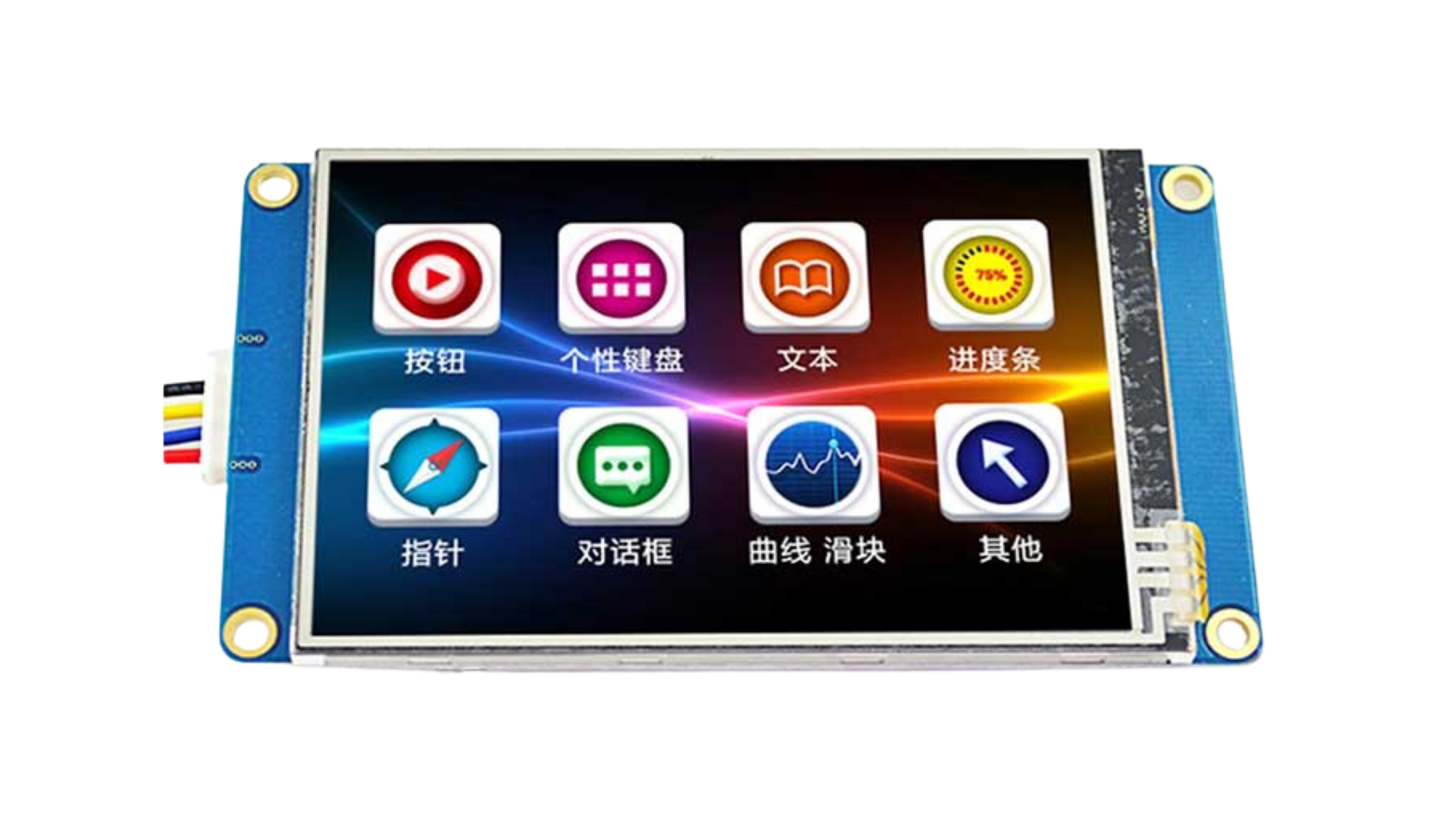
The Nextion display is a smart display module that integrates a touchscreen interface with a built-in microcontroller. It is designed to simplify the process of creating graphical user interfaces (GUIs) for embedded systems. By offloading the GUI processing to the display itself, the Nextion module reduces the workload on the host microcontroller or microprocessor.

Nextion displays are widely used in applications such as:

  • Home automation systems
  • Industrial control panels
  • IoT devices
  • Medical equipment
  • Automotive dashboards
  • Consumer electronics

With its user-friendly Nextion Editor software, developers can design and program GUIs without requiring advanced programming skills.

Explore Projects Built with Nextion display

Use Cirkit Designer to design, explore, and prototype these projects online. Some projects support real-time simulation. Click "Open Project" to start designing instantly!
Arduino Mega 2560 Controlled Automation System with 8-Channel Relay and Nextion Touch LCD Interface
Image of Capstone: A project utilizing Nextion display in a practical application
This circuit is centered around an Arduino Mega 2560, which controls a Nextion Touch LCD for user interface and a series of relays for switching various loads. The Arduino is powered by a 9V SMPS, and it drives an 8-channel 5V relay module to control devices like pumps, a loudspeaker, actuators, a heating plate, and a plucker. The relays are interfaced with solid-state relays (SSRs) and a thermistor for temperature sensing, enabling controlled power distribution to the connected devices based on programmed logic and user input.
Cirkit Designer LogoOpen Project in Cirkit Designer
Arduino Nano-Based OLED Clock with RTC and LiPo Battery Charging
Image of RTC for Keyboard: A project utilizing Nextion display in a practical application
This circuit features an Arduino Nano connected to an OLED display and a DS3231 real-time clock (RTC) module for displaying the current time. The Arduino Nano is powered through a toggle switch connected to its VIN pin, with power supplied by a TP4056 charging module that charges and manages two 3.7V LiPo batteries connected in parallel. The OLED and RTC module communicate with the Arduino via I2C, with shared SDA and SCL lines connected to the A4 and A5 pins of the Arduino, respectively.
Cirkit Designer LogoOpen Project in Cirkit Designer
Arduino Nano-Based Environmental Monitoring System with Nextion Touch LCD and CAN BUS Communication
Image of Circuito_CAIXAV2: A project utilizing Nextion display in a practical application
This circuit features an Arduino Nano microcontroller interfaced with a Nextion Touch LCD for user input/output, multiple SSR-10A solid-state relays for controlling high-power devices, and a single-channel relay for additional switching capabilities. It includes an Adafruit MCP9600 for temperature measurements, an MQ-5 gas sensor for detecting gas concentrations, a Hall effect sensor for magnetic field detection, and a CAN BUS module for vehicle communication. The circuit is powered by an LM2596 step-down module and includes various resistors for voltage/current adjustments and protection.
Cirkit Designer LogoOpen Project in Cirkit Designer
Arduino 101 OLED Display Animation Project
Image of wokwi animater test: A project utilizing Nextion display in a practical application
This circuit consists of an Arduino 101 microcontroller connected to a 0.96" OLED display via I2C communication. The Arduino runs a program that initializes the OLED and continuously displays an animated sequence of frames on the screen.
Cirkit Designer LogoOpen Project in Cirkit Designer

Explore Projects Built with Nextion display

Use Cirkit Designer to design, explore, and prototype these projects online. Some projects support real-time simulation. Click "Open Project" to start designing instantly!
Image of Capstone: A project utilizing Nextion display in a practical application
Arduino Mega 2560 Controlled Automation System with 8-Channel Relay and Nextion Touch LCD Interface
This circuit is centered around an Arduino Mega 2560, which controls a Nextion Touch LCD for user interface and a series of relays for switching various loads. The Arduino is powered by a 9V SMPS, and it drives an 8-channel 5V relay module to control devices like pumps, a loudspeaker, actuators, a heating plate, and a plucker. The relays are interfaced with solid-state relays (SSRs) and a thermistor for temperature sensing, enabling controlled power distribution to the connected devices based on programmed logic and user input.
Cirkit Designer LogoOpen Project in Cirkit Designer
Image of RTC for Keyboard: A project utilizing Nextion display in a practical application
Arduino Nano-Based OLED Clock with RTC and LiPo Battery Charging
This circuit features an Arduino Nano connected to an OLED display and a DS3231 real-time clock (RTC) module for displaying the current time. The Arduino Nano is powered through a toggle switch connected to its VIN pin, with power supplied by a TP4056 charging module that charges and manages two 3.7V LiPo batteries connected in parallel. The OLED and RTC module communicate with the Arduino via I2C, with shared SDA and SCL lines connected to the A4 and A5 pins of the Arduino, respectively.
Cirkit Designer LogoOpen Project in Cirkit Designer
Image of Circuito_CAIXAV2: A project utilizing Nextion display in a practical application
Arduino Nano-Based Environmental Monitoring System with Nextion Touch LCD and CAN BUS Communication
This circuit features an Arduino Nano microcontroller interfaced with a Nextion Touch LCD for user input/output, multiple SSR-10A solid-state relays for controlling high-power devices, and a single-channel relay for additional switching capabilities. It includes an Adafruit MCP9600 for temperature measurements, an MQ-5 gas sensor for detecting gas concentrations, a Hall effect sensor for magnetic field detection, and a CAN BUS module for vehicle communication. The circuit is powered by an LM2596 step-down module and includes various resistors for voltage/current adjustments and protection.
Cirkit Designer LogoOpen Project in Cirkit Designer
Image of wokwi animater test: A project utilizing Nextion display in a practical application
Arduino 101 OLED Display Animation Project
This circuit consists of an Arduino 101 microcontroller connected to a 0.96" OLED display via I2C communication. The Arduino runs a program that initializes the OLED and continuously displays an animated sequence of frames on the screen.
Cirkit Designer LogoOpen Project in Cirkit Designer

Technical Specifications

Below are the key technical details for the Nextion display (specific values may vary depending on the model):

Parameter Specification
Display Type TFT LCD with resistive or capacitive touchscreen
Screen Sizes 2.4", 2.8", 3.2", 3.5", 4.3", 5.0", 7.0", etc.
Resolution 320x240 (QVGA) to 1024x600 (depending on model)
Communication Interface UART (TTL, 3.3V or 5V logic levels)
Input Voltage 4.75V to 7V (via external power supply)
Power Consumption ~200mA (varies by model and brightness settings)
Flash Memory 4MB to 16MB (for GUI storage)
RAM 3584 bytes
Operating Temperature -20°C to 70°C
Touchscreen Type Resistive or Capacitive (model-dependent)

Pin Configuration and Descriptions

The Nextion display typically has a 4-pin interface for communication and power:

Pin Name Description
1 VCC Power supply input (4.75V to 7V)
2 GND Ground
3 TX UART Transmit (data sent from Nextion to host)
4 RX UART Receive (data sent from host to Nextion)

Usage Instructions

Connecting the Nextion Display to an Arduino UNO

To use the Nextion display with an Arduino UNO, follow these steps:

  1. Wiring:

    • Connect the VCC pin of the Nextion display to the 5V pin on the Arduino.
    • Connect the GND pin of the Nextion display to the GND pin on the Arduino.
    • Connect the TX pin of the Nextion display to the Arduino's digital pin 2 (via a voltage divider if required).
    • Connect the RX pin of the Nextion display to the Arduino's digital pin 3.
  2. Install the Nextion Library:

    • Download and install the official Nextion library from the Arduino IDE Library Manager.
  3. Design the GUI:

    • Use the Nextion Editor software to design your GUI. Upload the .tft file to the display using a microSD card.
  4. Arduino Code Example: Below is an example code snippet to display a message on the Nextion display:

    #include <Nextion.h>
    
    // Define Nextion objects (page ID, component ID, component name)
    NexText t0 = NexText(0, 1, "t0"); // Textbox on page 0, ID 1, named "t0"
    
    // Define software serial for communication
    #include <SoftwareSerial.h>
    SoftwareSerial nextion(2, 3); // RX, TX
    
    void setup() {
      // Initialize serial communication with Nextion
      nextion.begin(9600);
      Serial.begin(9600);
    
      // Initialize the Nextion library
      nexInit();
    
      // Set initial text on the display
      t0.setText("Hello, Nextion!");
    }
    
    void loop() {
      // Handle any incoming events from the Nextion display
      nexLoop(nex_listen_list);
    }
    

    Note: Ensure the baud rate in the Nextion Editor matches the baud rate in the Arduino code.

Important Considerations and Best Practices

  • Power Supply: Use a stable power source to avoid display flickering or unexpected resets.
  • Voltage Levels: Ensure the UART communication voltage levels match (3.3V or 5V). Use a voltage divider or level shifter if necessary.
  • GUI Design: Optimize your GUI design to minimize memory usage and improve performance.
  • Debugging: Use the Nextion Editor's simulator to test your GUI before uploading it to the hardware.

Troubleshooting and FAQs

Common Issues and Solutions

  1. Display Not Powering On:

    • Verify the power supply voltage and current are within the specified range.
    • Check the wiring connections for loose or incorrect connections.
  2. No Communication Between Arduino and Nextion:

    • Ensure the TX and RX pins are correctly connected.
    • Verify the baud rate in the Arduino code matches the Nextion display settings.
    • Check for proper grounding between the Arduino and the Nextion display.
  3. GUI Not Displaying Correctly:

    • Confirm the .tft file was uploaded correctly to the display via the microSD card.
    • Ensure the GUI design is compatible with the display's resolution.
  4. Touchscreen Not Responding:

    • Check if the touchscreen type (resistive or capacitive) matches your expectations.
    • Verify the GUI design includes touch-enabled components.

FAQs

Q: Can I use the Nextion display with other microcontrollers?
A: Yes, the Nextion display can be used with any microcontroller or microprocessor that supports UART communication, such as ESP32, Raspberry Pi, or STM32.

Q: How do I update the firmware on the Nextion display?
A: Use the Nextion Editor to generate a .tft file and upload it to the display via a microSD card.

Q: Can I use multiple Nextion displays in a single project?
A: Yes, you can use multiple displays by connecting them to separate UART ports or using a multiplexer.

Q: Is the Nextion Editor software free?
A: Yes, the Nextion Editor is free to download and use for designing GUIs.