How to Use NEO 6M GPS MODULE: Examples, Pinouts, and Specs
Introduction
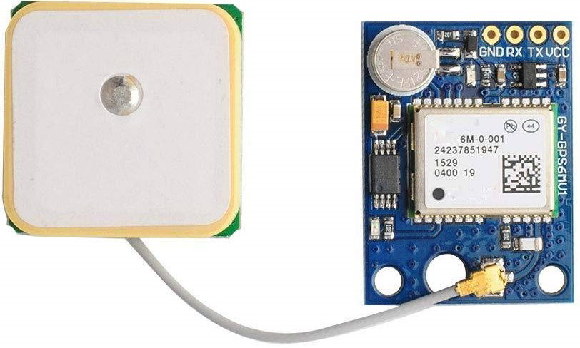
The NEO 6M GPS Module, manufactured by ESP (Part ID: GPS), is a compact and highly sensitive GPS receiver designed to provide accurate positioning data using the Global Positioning System. This module is widely used in navigation, tracking, and location-based services due to its low power consumption and reliable performance. It is ideal for applications such as vehicle tracking, drones, robotics, and outdoor navigation systems.
Explore Projects Built with NEO 6M GPS MODULE

Explore Projects Built with NEO 6M GPS MODULE
Technical Specifications
The NEO 6M GPS Module is equipped with advanced features to ensure precise and efficient operation. Below are the key technical details and pin configuration:
Key Technical Details
| Parameter | Specification |
|---|---|
| Manufacturer | ESP |
| Part ID | GPS |
| Input Voltage | 3.3V to 5V |
| Operating Current | 45mA (typical) |
| Communication Interface | UART (9600 baud rate by default) |
| Positioning Accuracy | 2.5 meters (CEP) |
| Cold Start Time | 27 seconds (typical) |
| Hot Start Time | 1 second (typical) |
| Antenna | External active antenna (included) |
| Dimensions | 25mm x 35mm x 6mm |
Pin Configuration and Descriptions
| Pin Name | Pin Number | Description |
|---|---|---|
| VCC | 1 | Power input (3.3V to 5V) |
| GND | 2 | Ground |
| TX | 3 | UART Transmit (data output) |
| RX | 4 | UART Receive (data input) |
| PPS | 5 | Pulse Per Second (timing signal output) |
Usage Instructions
The NEO 6M GPS Module is straightforward to use in a circuit. Below are the steps and best practices for integrating it into your project:
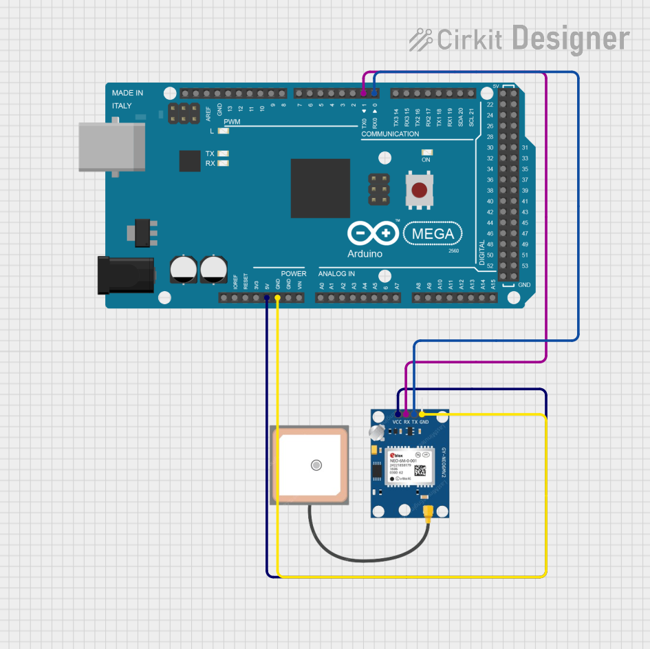
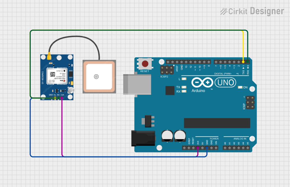
Connecting the Module
- Power Supply: Connect the
VCCpin to a 3.3V or 5V power source and theGNDpin to ground. - UART Communication:
- Connect the
TXpin of the module to theRXpin of your microcontroller (e.g., Arduino UNO). - Connect the
RXpin of the module to theTXpin of your microcontroller.
- Connect the
- Antenna: Ensure the external active antenna is securely connected to the module for optimal signal reception.
Important Considerations
- Place the module in an open area with a clear view of the sky for better GPS signal reception.
- Avoid placing the module near sources of electromagnetic interference (e.g., motors, power supplies).
- Use a level shifter if your microcontroller operates at 3.3V logic levels to avoid damaging the module.
Example Code for Arduino UNO
Below is an example code snippet to interface the NEO 6M GPS Module with an Arduino UNO. This code uses the TinyGPS++ library to parse GPS data.
#include <TinyGPS++.h>
#include <SoftwareSerial.h>

// Create a TinyGPS++ object to parse GPS data
TinyGPSPlus gps;

// Define RX and TX pins for SoftwareSerial
SoftwareSerial gpsSerial(4, 3); // RX = Pin 4, TX = Pin 3

void setup() {
  Serial.begin(9600); // Initialize Serial Monitor at 9600 baud
  gpsSerial.begin(9600); // Initialize GPS module at 9600 baud
  Serial.println("NEO 6M GPS Module Test");
}

void loop() {
  // Check if data is available from the GPS module
  while (gpsSerial.available() > 0) {
    char c = gpsSerial.read(); // Read a character from the GPS module
    if (gps.encode(c)) { // Parse the character using TinyGPS++
      if (gps.location.isUpdated()) { // Check if location data is updated
        Serial.print("Latitude: ");
        Serial.println(gps.location.lat(), 6); // Print latitude
        Serial.print("Longitude: ");
        Serial.println(gps.location.lng(), 6); // Print longitude
        Serial.print("Altitude: ");
        Serial.println(gps.altitude.meters()); // Print altitude in meters
      }
    }
  }
}
Notes:
- Install the
TinyGPS++library in the Arduino IDE before uploading the code. - Replace
4and3inSoftwareSerial gpsSerial(4, 3)with the pins you are using for RX and TX.
Troubleshooting and FAQs
Common Issues
No GPS Data Received:
- Ensure the module has a clear view of the sky.
- Verify the connections between the module and the microcontroller.
- Check the baud rate settings in the code (default is 9600).
Incorrect or Inconsistent Data:
- Ensure the antenna is securely connected and positioned correctly.
- Avoid placing the module near sources of interference.
Module Not Powering On:
- Verify the power supply voltage (3.3V to 5V).
- Check for loose or incorrect connections.
FAQs
Q: Can the NEO 6M GPS Module work indoors?
A: The module may work indoors near windows, but signal reception is significantly better outdoors.
Q: How do I change the baud rate of the module?
A: You can use specific configuration commands sent via UART to change the baud rate. Refer to the module's datasheet for details.
Q: What is the purpose of the PPS pin?
A: The PPS (Pulse Per Second) pin provides a precise timing signal that can be used for synchronization in time-sensitive applications.
By following this documentation, you can effectively integrate and use the NEO 6M GPS Module in your projects.