How to Use Pulsante arresto: Examples, Pinouts, and Specs
Introduction
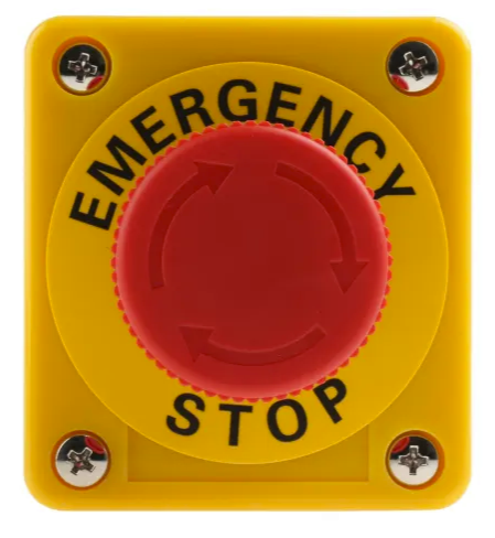
The Pulsante Arresto (Stop Button) is a safety-critical electronic component designed to interrupt the operation of a circuit or device. It is commonly used in industrial, commercial, and consumer applications where immediate cessation of functionality is required to ensure safety or prevent damage. The button is typically large, easy to press, and often colored red for high visibility.
Explore Projects Built with Pulsante arresto


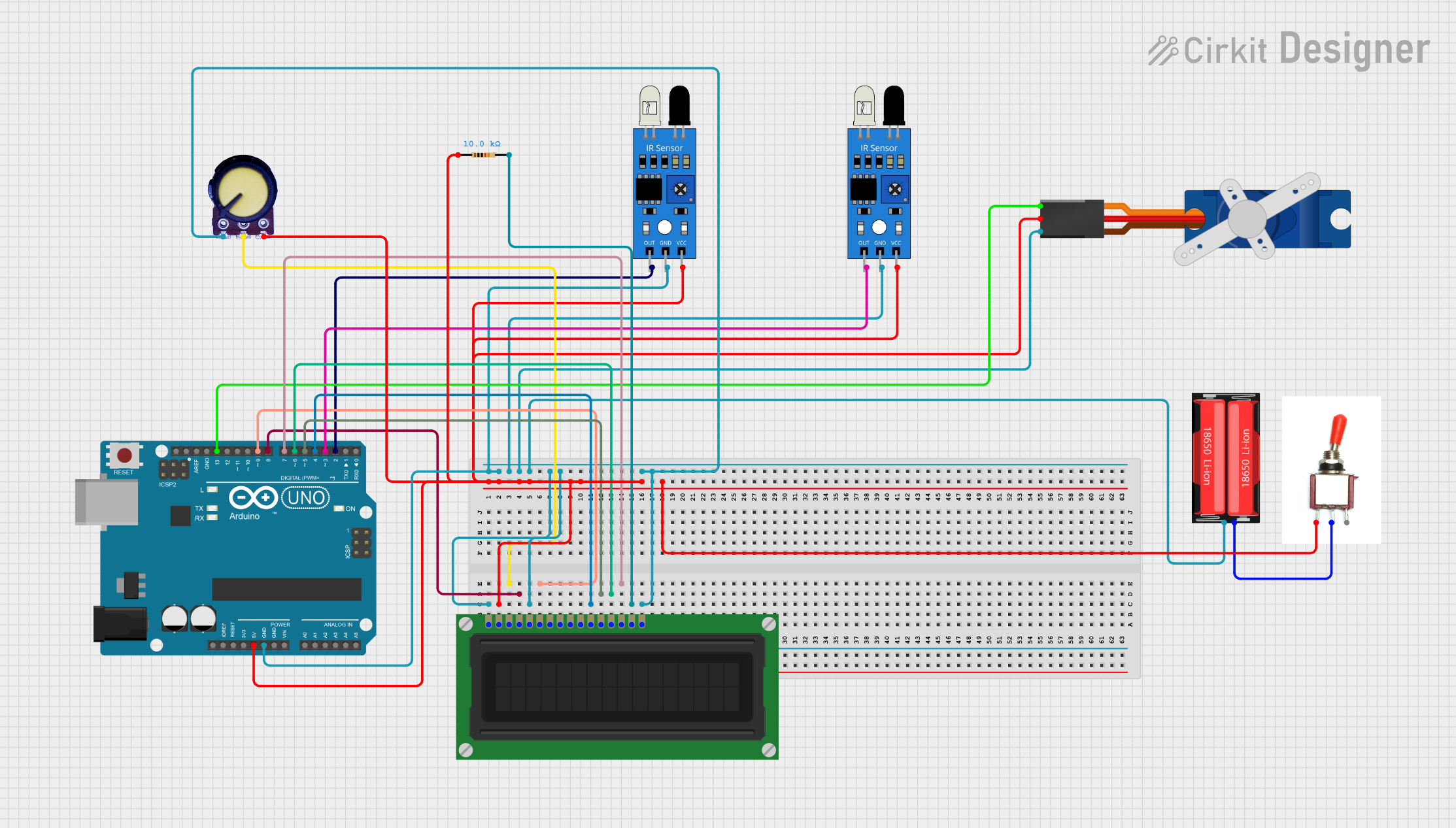
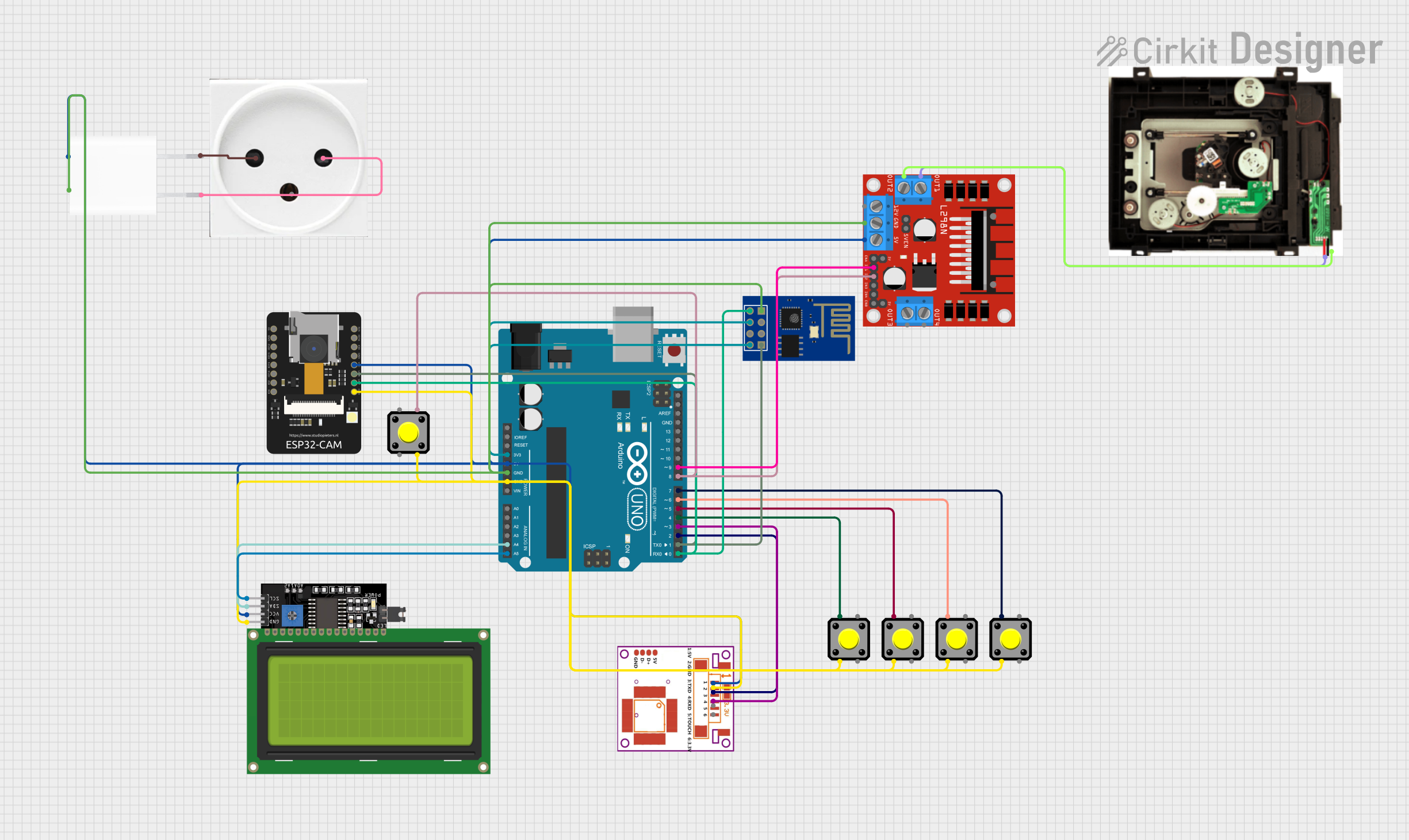
Explore Projects Built with Pulsante arresto
Common Applications and Use Cases
- Emergency stop mechanisms in industrial machinery
- Safety cut-off switches in consumer appliances
- Power interruption in robotics and automation systems
- Circuit reset functionality in testing and prototyping environments
Technical Specifications
Key Technical Details
| Parameter | Value |
|---|---|
| Operating Voltage | 12V to 250V AC/DC |
| Maximum Current Rating | 10A |
| Contact Configuration | Normally Open (NO) or Normally Closed (NC) |
| Mechanical Durability | 50,000 cycles |
| Operating Temperature | -25°C to +70°C |
| Mounting Hole Diameter | 22mm |
| Material | Plastic housing with metal contacts |
Pin Configuration and Descriptions
The Pulsante Arresto typically has two or four terminals, depending on its configuration (NO or NC). Below is a table describing the pin connections:
| Pin Label | Description |
|---|---|
| NO | Normally Open contact; closes when the button is pressed |
| NC | Normally Closed contact; opens when the button is pressed |
| COM | Common terminal for connecting the circuit |
Usage Instructions
How to Use the Component in a Circuit
- Determine the Contact Configuration: Identify whether the button is configured as Normally Open (NO) or Normally Closed (NC). This will dictate how it interacts with your circuit.
- Connect the Terminals:
- For an NO configuration, connect one terminal to the power source and the other to the load or control circuit.
- For an NC configuration, connect the terminals in series with the circuit you wish to interrupt.
- Mount the Button: Secure the button in a 22mm mounting hole, ensuring it is easily accessible for operation.
- Test the Circuit: Verify that pressing the button interrupts the circuit as intended.
Important Considerations and Best Practices
- Safety First: Always disconnect power before wiring the button to avoid electric shock.
- Debouncing: If the button is used in a digital circuit, consider implementing a debouncing mechanism to prevent false triggering.
- Visibility: Install the button in a location where it is easily visible and accessible in case of an emergency.
- Load Ratings: Ensure the button's voltage and current ratings are compatible with your circuit to prevent overheating or damage.
Example: Connecting to an Arduino UNO
The Pulsante Arresto can be used with an Arduino UNO to create a simple emergency stop mechanism. Below is an example circuit and code:
Circuit Description
- Connect the NO terminal of the button to digital pin 2 on the Arduino.
- Connect the COM terminal to the ground (GND) pin on the Arduino.
- Use an external pull-up resistor (10kΩ) between digital pin 2 and 5V to ensure a stable signal.
Arduino Code
// Pulsante Arresto Example with Arduino UNO
// This code monitors the stop button and turns off an LED when pressed.

const int stopButtonPin = 2; // Pin connected to the stop button
const int ledPin = 13;       // Pin connected to the onboard LED

void setup() {
  pinMode(stopButtonPin, INPUT_PULLUP); // Configure button pin as input with pull-up
  pinMode(ledPin, OUTPUT);             // Configure LED pin as output
  digitalWrite(ledPin, HIGH);          // Turn on the LED initially
}

void loop() {
  int buttonState = digitalRead(stopButtonPin); // Read the button state

  if (buttonState == LOW) { // Button pressed (active LOW)
    digitalWrite(ledPin, LOW); // Turn off the LED
  } else {
    digitalWrite(ledPin, HIGH); // Keep the LED on
  }
}
Troubleshooting and FAQs
Common Issues Users Might Face
Button Does Not Interrupt the Circuit:
- Cause: Incorrect wiring of the terminals.
- Solution: Double-check the connections and ensure the correct terminals (NO or NC) are used.
Button Fails to Reset:
- Cause: Mechanical wear or debris inside the button.
- Solution: Inspect the button for physical damage or obstructions and replace if necessary.
Arduino Does Not Detect Button Press:
- Cause: Missing pull-up resistor or incorrect pin configuration.
- Solution: Use an internal or external pull-up resistor and verify the pinMode configuration in the code.
Solutions and Tips for Troubleshooting
- Use a multimeter to test the continuity of the button's terminals when pressed and released.
- Ensure the button's voltage and current ratings are not exceeded in your circuit.
- For digital circuits, implement software debouncing to avoid erratic behavior caused by mechanical bounce.
By following this documentation, you can safely and effectively integrate the Pulsante Arresto into your projects, ensuring reliable operation and enhanced safety.