How to Use N20 6V: Examples, Pinouts, and Specs
Introduction
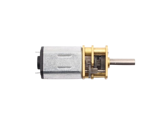
The N20 6V is a small DC motor manufactured by Arduino (Part ID: uno). It is widely recognized for its compact size, moderate torque, and versatility in various applications. This motor is ideal for robotics, hobby projects, and small mechanical systems where space is limited but reliable performance is required. Its 6V rating makes it compatible with a variety of power sources, including batteries and microcontroller-based systems.
Explore Projects Built with N20 6V
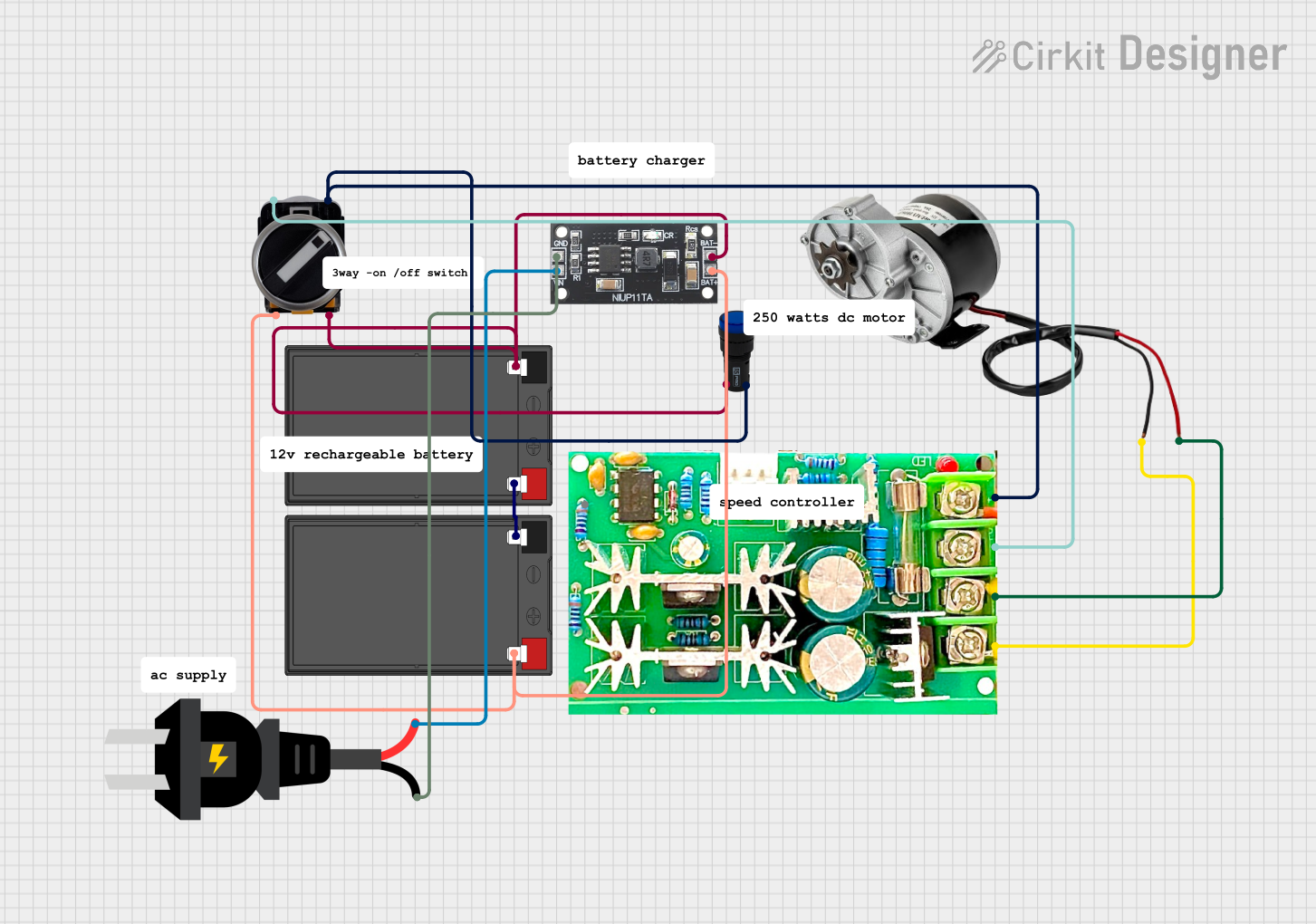


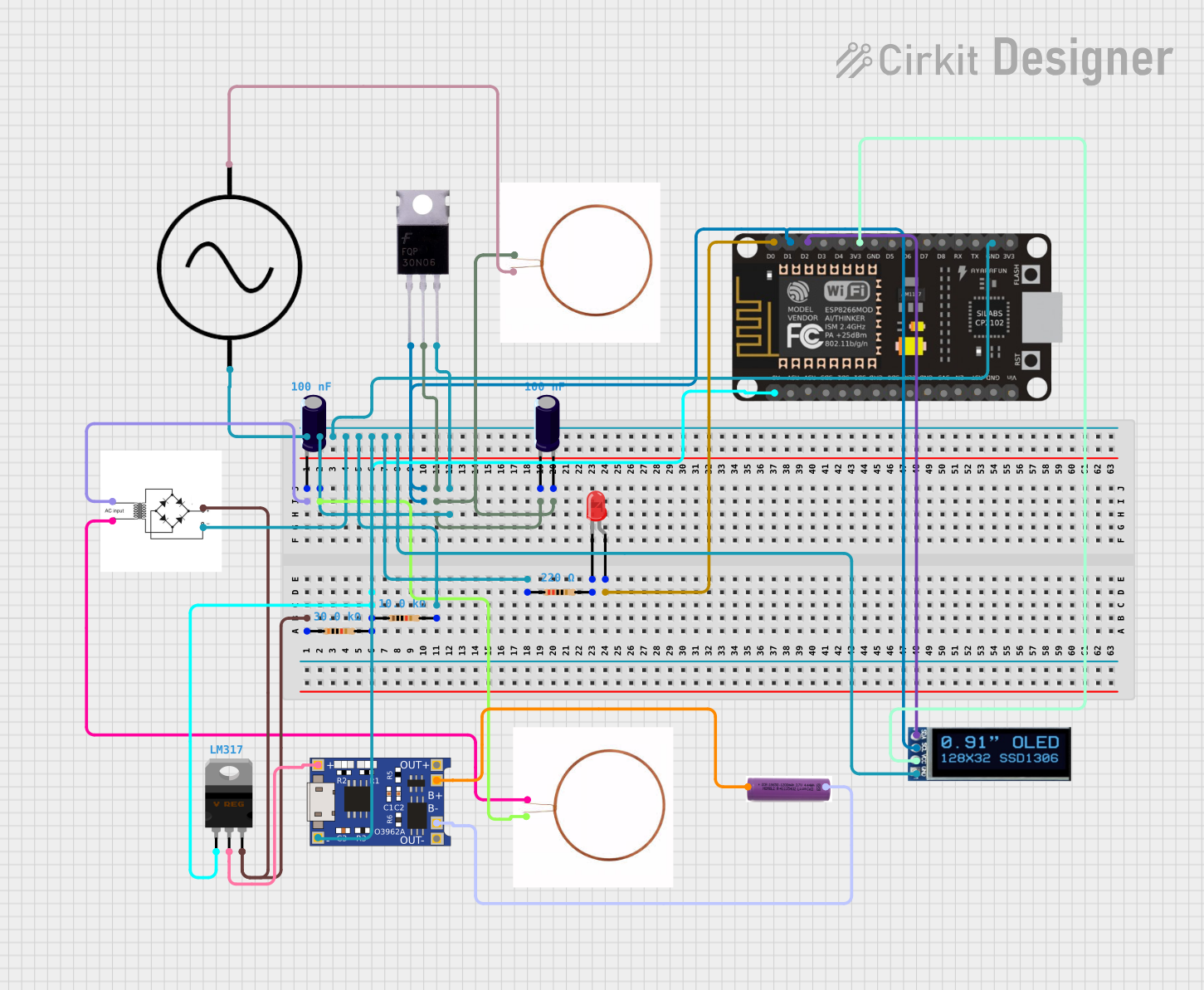
Explore Projects Built with N20 6V
Common Applications
- Robotics (e.g., driving wheels or actuators)
- Small conveyor systems
- DIY hobby projects
- Educational kits and prototypes
- Automated mechanisms (e.g., door locks, small pumps)
Technical Specifications
The N20 6V motor is designed to deliver reliable performance in a compact form factor. Below are its key technical details:
| Parameter | Value |
|---|---|
| Rated Voltage | 6V |
| Operating Voltage Range | 3V - 6V |
| No-Load Speed | ~200 RPM (at 6V) |
| No-Load Current | ~40 mA |
| Stall Current | ~1.2 A |
| Stall Torque | ~0.3 kg.cm |
| Shaft Diameter | 3 mm |
| Motor Dimensions | 12 mm x 10 mm x 15 mm |
| Weight | ~10 g |
Pin Configuration and Descriptions
The N20 6V motor has two terminals for electrical connections:
| Pin | Description |
|---|---|
| Pin 1 | Positive terminal (connect to +6V) |
| Pin 2 | Negative terminal (connect to GND) |
Note: The motor's direction of rotation can be reversed by swapping the polarity of the connections.
Usage Instructions
How to Use the N20 6V Motor in a Circuit
- Power Supply: Ensure the motor is powered within its operating voltage range (3V to 6V). Exceeding 6V may damage the motor.
- Motor Driver: Use a motor driver (e.g., L298N or L293D) to control the motor, especially if you plan to use it with a microcontroller like the Arduino UNO. Directly connecting the motor to a microcontroller pin is not recommended due to the high current draw.
- Polarity: Connect the motor terminals to the motor driver outputs. The polarity determines the direction of rotation.
- PWM Control: Use Pulse Width Modulation (PWM) to control the motor's speed. Most motor drivers support PWM input.
Example: Connecting the N20 6V Motor to an Arduino UNO
Below is an example of how to control the N20 6V motor using an Arduino UNO and an L298N motor driver.
Circuit Connections
- Connect the motor terminals to the
OUT1andOUT2pins of the L298N driver. - Connect the
IN1andIN2pins of the L298N to Arduino digital pins 9 and 10, respectively. - Connect the
ENApin of the L298N to Arduino digital pin 3 for PWM speed control. - Provide a 6V power supply to the motor driver.
Arduino Code
// Define motor control pins
const int IN1 = 9;  // Motor direction pin 1
const int IN2 = 10; // Motor direction pin 2
const int ENA = 3;  // PWM speed control pin

void setup() {
  // Set motor control pins as outputs
  pinMode(IN1, OUTPUT);
  pinMode(IN2, OUTPUT);
  pinMode(ENA, OUTPUT);
}

void loop() {
  // Rotate motor in one direction
  digitalWrite(IN1, HIGH); // Set IN1 high
  digitalWrite(IN2, LOW);  // Set IN2 low
  analogWrite(ENA, 128);   // Set speed to 50% (PWM value: 128)

  delay(2000); // Run motor for 2 seconds

  // Stop the motor
  analogWrite(ENA, 0); // Set speed to 0
  delay(1000);         // Wait for 1 second

  // Rotate motor in the opposite direction
  digitalWrite(IN1, LOW);  // Set IN1 low
  digitalWrite(IN2, HIGH); // Set IN2 high
  analogWrite(ENA, 128);   // Set speed to 50% (PWM value: 128)

  delay(2000); // Run motor for 2 seconds

  // Stop the motor
  analogWrite(ENA, 0); // Set speed to 0
  delay(1000);         // Wait for 1 second
}
Important Considerations
- Current Limiting: Use a motor driver capable of handling the stall current (~1.2 A) to prevent damage.
- Heat Management: Prolonged operation at high loads may cause the motor to heat up. Allow cooling periods if necessary.
- Noise Suppression: Add a small ceramic capacitor (e.g., 0.1 µF) across the motor terminals to reduce electrical noise.
Troubleshooting and FAQs
Common Issues and Solutions
Motor Does Not Spin
- Cause: Insufficient power supply or incorrect wiring.
- Solution: Verify the power supply voltage and check all connections.
Motor Spins in the Wrong Direction
- Cause: Polarity of the motor terminals is reversed.
- Solution: Swap the connections to the motor terminals.
Motor Overheats
- Cause: Prolonged operation at high loads or exceeding the voltage rating.
- Solution: Reduce the load or ensure the supply voltage does not exceed 6V.
Motor Vibrates but Does Not Rotate
- Cause: Insufficient torque or mechanical obstruction.
- Solution: Check for obstructions and ensure the motor is not overloaded.
FAQs
Q: Can I power the N20 6V motor directly from an Arduino UNO?
A: No, the Arduino UNO cannot supply the required current for the motor. Use a motor driver or external power source.
Q: How can I control the speed of the motor?
A: Use PWM (Pulse Width Modulation) via a motor driver to adjust the motor's speed.
Q: Is the N20 6V motor suitable for continuous operation?
A: While the motor can handle continuous operation, ensure it does not overheat by monitoring the load and providing cooling periods if necessary.
Q: Can I use the N20 6V motor with a 12V power supply?
A: No, using a 12V power supply will damage the motor. Stick to the recommended voltage range of 3V to 6V.