How to Use DC MCB circuit breaker: Examples, Pinouts, and Specs
Introduction
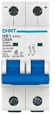
The CHINT NB1-63DC is a DC Miniature Circuit Breaker (MCB) designed to provide reliable protection for DC electrical circuits. It automatically disconnects the circuit in the event of an overload or short circuit, ensuring safety and preventing damage to connected components. This MCB is widely used in renewable energy systems, industrial automation, and other DC power applications.
Explore Projects Built with DC MCB circuit breaker


Explore Projects Built with DC MCB circuit breaker
Common Applications and Use Cases
- Solar photovoltaic (PV) systems
- Battery energy storage systems
- Electric vehicle (EV) charging stations
- DC motor protection
- Industrial control panels
- Telecommunications equipment
Technical Specifications
Key Technical Details
| Parameter | Specification |
|---|---|
| Manufacturer | CHINT |
| Part Number | NB1-63DC |
| Rated Voltage | 250V DC (1-pole), 500V DC (2-pole) |
| Rated Current | 1A to 63A (varies by model) |
| Breaking Capacity | 10kA |
| Number of Poles | 1P, 2P |
| Tripping Curve | C curve |
| Operating Temperature Range | -30°C to +70°C |
| Mounting Type | DIN rail (35mm) |
| Standards Compliance | IEC/EN 60947-2, GB/T 14048.2 |
Pin Configuration and Descriptions
The CHINT NB1-63DC has screw terminals for input and output connections. Below is the terminal configuration:
| Terminal Label | Description |
|---|---|
| L+ | Positive input terminal (Line) |
| L- | Negative input terminal (Line) |
| T+ | Positive output terminal (Load) |
| T- | Negative output terminal (Load) |
Note: For 2-pole models, the terminals are duplicated for both poles.
Usage Instructions
How to Use the Component in a Circuit
- Determine the Rated Current: Select the appropriate NB1-63DC model based on the current rating of your circuit (e.g., 10A, 16A, etc.).
- Mounting: Install the MCB on a standard 35mm DIN rail in your distribution box or control panel.
- Wiring:
- Connect the DC power source to the input terminals (L+ and L-).
- Connect the load (e.g., DC motor, battery, or other equipment) to the output terminals (T+ and T-).
- Ensure proper polarity is maintained during wiring.
- Testing:
- After installation, switch on the MCB and verify that the circuit operates correctly.
- Test the tripping mechanism by simulating an overload or short circuit condition.
Important Considerations and Best Practices
- Polarity: Always maintain correct polarity when wiring the MCB. Reversing polarity may damage the device or connected components.
- Voltage Rating: Ensure the operating voltage of the circuit does not exceed the rated voltage of the MCB (250V DC for 1-pole, 500V DC for 2-pole).
- Current Rating: Select an MCB with a current rating slightly higher than the normal operating current of your circuit but lower than the maximum current the wiring can handle.
- Environmental Conditions: Avoid installing the MCB in environments with excessive moisture, dust, or extreme temperatures outside the specified range (-30°C to +70°C).
- Periodic Testing: Regularly test the MCB to ensure it functions correctly and trips under fault conditions.
Example: Connecting to a Solar PV System
In a solar PV system, the NB1-63DC can be used to protect the DC circuit between the solar panels and the charge controller. Below is a simplified connection diagram:
Solar Panel (+) ----> L+ (MCB Input)
Solar Panel (-) ----> L- (MCB Input)
T+ (MCB Output) ----> Charge Controller (+)
T- (MCB Output) ----> Charge Controller (-)
Troubleshooting and FAQs
Common Issues and Solutions
| Issue | Possible Cause | Solution |
|---|---|---|
| MCB does not trip during a fault | Fault current is below the trip threshold | Verify the fault current and ensure it exceeds the MCB's rated trip current. |
| MCB trips frequently | Overloaded circuit or short circuit | Check the circuit for overloads or shorts. Reduce the load or fix the fault. |
| MCB does not power on | Loose or incorrect wiring | Verify all connections and ensure proper polarity. |
| MCB overheats during operation | Poor ventilation or excessive current | Ensure adequate ventilation and verify the current does not exceed the MCB's rating. |
FAQs
Q1: Can the NB1-63DC be used in AC circuits?
A1: No, the NB1-63DC is specifically designed for DC circuits. For AC applications, use an AC-rated MCB.
Q2: How do I select the correct tripping curve?
A2: The NB1-63DC uses a C curve, which is suitable for most general-purpose DC applications. For specialized applications, consult CHINT's technical support.
Q3: Can I use the NB1-63DC in a high-altitude environment?
A3: Yes, but the breaking capacity may be reduced at altitudes above 2000 meters. Refer to the manufacturer's guidelines for derating information.
Q4: How often should I test the MCB?
A4: It is recommended to test the MCB at least once a year to ensure proper functionality.
By following this documentation, users can safely and effectively integrate the CHINT NB1-63DC into their DC circuits.