How to Use MT4W-DA-4N: Examples, Pinouts, and Specs
Introduction
The MT4W-DA-4N is a 4-channel digital-to-analog converter (DAC) module designed for high-precision signal generation. It is widely used in applications requiring accurate analog signal outputs, such as industrial automation, control systems, and laboratory instrumentation. This module converts digital signals into precise analog voltages, making it ideal for interfacing with microcontrollers, PLCs, and other digital systems.
Explore Projects Built with MT4W-DA-4N


Explore Projects Built with MT4W-DA-4N
Common Applications and Use Cases
- Industrial automation and process control
- Signal generation for testing and measurement
- Analog control of actuators, motors, and valves
- Laboratory instrumentation and data acquisition systems
- Audio signal processing
Technical Specifications
The MT4W-DA-4N is engineered for reliability and precision. Below are its key technical specifications:
General Specifications
| Parameter | Value |
|---|---|
| Number of Channels | 4 |
| Output Voltage Range | 0–10 V (programmable) |
| Resolution | 12-bit (4096 steps) |
| Maximum Output Current | 10 mA per channel |
| Input Signal Type | Digital (SPI or I2C interface) |
| Power Supply Voltage | 12–24 V DC |
| Operating Temperature | -10°C to 55°C |
| Dimensions | 72 mm x 48 mm x 25 mm |
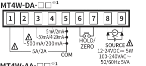
Pin Configuration and Descriptions
The MT4W-DA-4N features a standard pinout for easy integration into circuits. Below is the pin configuration:
| Pin Number | Pin Name | Description |
|---|---|---|
| 1 | VCC | Power supply input (12–24 V DC) |
| 2 | GND | Ground connection |
| 3 | SCL | Serial Clock Line (for I2C communication) |
| 4 | SDA | Serial Data Line (for I2C communication) |
| 5 | CS | Chip Select (for SPI communication) |
| 6 | MOSI | Master Out Slave In (for SPI communication) |
| 7 | MISO | Master In Slave Out (for SPI communication) |
| 8 | CLK | Clock signal (for SPI communication) |
| 9–12 | OUT1–OUT4 | Analog output channels 1 to 4 |
Usage Instructions
The MT4W-DA-4N is straightforward to use in a circuit. Follow the steps below to integrate it into your system:
Step 1: Power Supply
- Connect the VCC pin to a 12–24 V DC power source.
- Connect the GND pin to the ground of your circuit.
Step 2: Communication Interface
- For I2C communication:
- Connect the SCL pin to the I2C clock line of your microcontroller.
- Connect the SDA pin to the I2C data line of your microcontroller.
- For SPI communication:
- Connect the CS, MOSI, MISO, and CLK pins to the corresponding SPI pins on your microcontroller.
Step 3: Analog Outputs
- Connect the OUT1–OUT4 pins to the devices or circuits requiring analog signals.
- Ensure the connected devices do not exceed the maximum output current of 10 mA per channel.
Step 4: Programming
- Configure your microcontroller to send digital data to the MT4W-DA-4N using the selected communication protocol (I2C or SPI).
- Use the following example code for Arduino UNO with I2C communication:
#include <Wire.h> // Include the Wire library for I2C communication

#define DAC_I2C_ADDRESS 0x48 // Replace with the actual I2C address of MT4W-DA-4N

void setup() {
  Wire.begin(); // Initialize I2C communication
  Serial.begin(9600); // Initialize serial communication for debugging
}

void loop() {
  // Example: Set channel 1 to output 5V
  uint8_t channel = 0x01; // Channel 1
  uint16_t value = 2048;  // 50% of 12-bit range (5V for 0-10V output)

  sendDACValue(channel, value);
  delay(1000); // Wait for 1 second
}

void sendDACValue(uint8_t channel, uint16_t value) {
  Wire.beginTransmission(DAC_I2C_ADDRESS); // Start communication with DAC
  Wire.write(channel); // Send the channel number
  Wire.write(value >> 8); // Send the high byte of the 12-bit value
  Wire.write(value & 0xFF); // Send the low byte of the 12-bit value
  Wire.endTransmission(); // End communication

  Serial.print("Channel ");
  Serial.print(channel);
  Serial.print(" set to value: ");
  Serial.println(value);
}
Important Considerations and Best Practices
- Ensure the power supply voltage is within the specified range (12–24 V DC).
- Avoid exceeding the maximum output current of 10 mA per channel to prevent damage.
- Use appropriate pull-up resistors for I2C communication if not already included in your circuit.
- Shield the module and communication lines from electrical noise in industrial environments.
Troubleshooting and FAQs
Common Issues and Solutions
No Output Signal
- Verify that the power supply is connected and within the specified voltage range.
- Check the communication interface (I2C or SPI) for proper connections and configuration.
- Ensure the correct channel and value are being sent to the DAC.
Incorrect Output Voltage
- Confirm that the digital value sent corresponds to the desired analog voltage.
- Check for any load connected to the output that may exceed the maximum current rating.
Communication Failure
- Ensure the I2C or SPI address matches the configuration in your code.
- Verify the pull-up resistors for I2C lines are correctly installed if required.
- Check for loose or incorrect wiring between the microcontroller and the DAC module.
FAQs
Q: Can I use the MT4W-DA-4N with a 5V microcontroller?
A: Yes, but you may need level shifters for the communication lines if the microcontroller operates at 5V logic levels.
Q: What is the resolution of the analog output?
A: The MT4W-DA-4N has a 12-bit resolution, providing 4096 discrete output levels.
Q: Can I use all four channels simultaneously?
A: Yes, all four channels can be used simultaneously, provided the total current does not exceed the module's specifications.
Q: Is the module compatible with Arduino?
A: Yes, the MT4W-DA-4N can be easily interfaced with Arduino using I2C or SPI communication protocols.