How to Use DIP Switch 4 Position: Examples, Pinouts, and Specs
Introduction
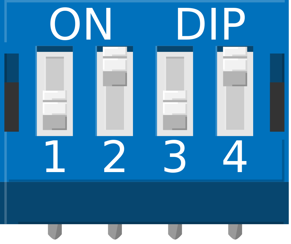
A DIP (Dual Inline Package) switch is a manual electronic switch that is commonly used in circuit boards to select between multiple options. The DIP switch 4 position consists of four individual switches packaged together, with each switch capable of being toggled on or off independently. This allows for 16 unique binary configurations, making it an ideal component for setting hardware addresses, configuration parameters, or mode selections without the need for software intervention. Common applications include computer peripherals, remote controls, and industrial control systems.
Explore Projects Built with DIP Switch 4 Position
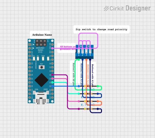

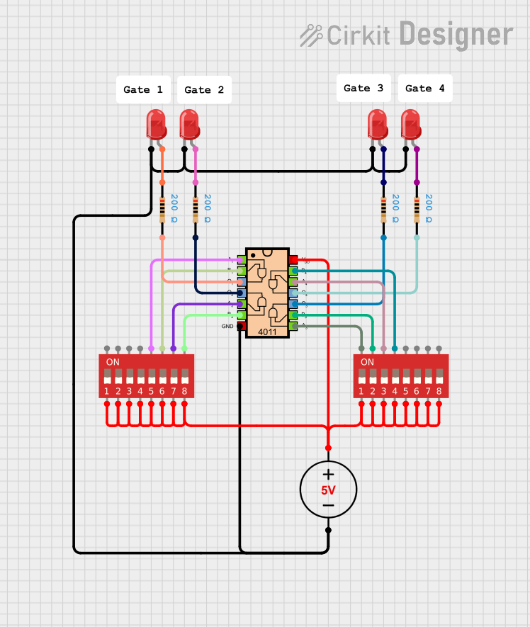
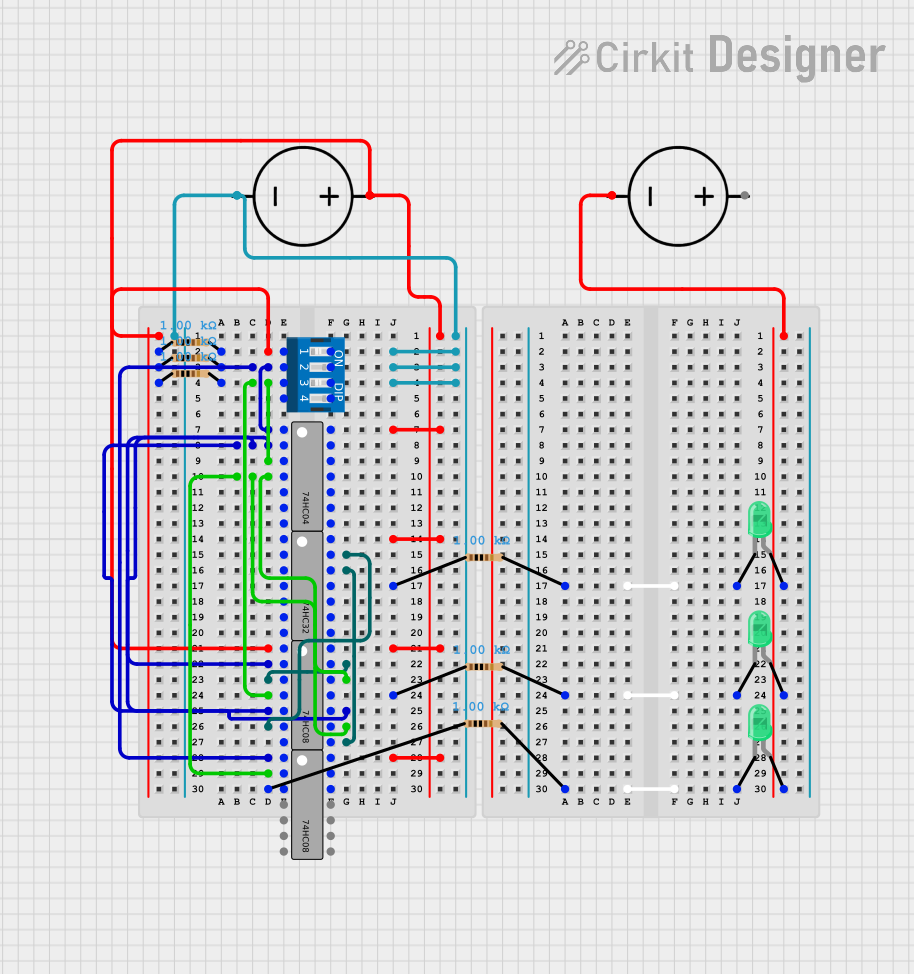
Explore Projects Built with DIP Switch 4 Position
Technical Specifications
General Characteristics
- Switch Type: SPST (Single Pole, Single Throw)
- Number of Positions: 4
- Contact Rating: Typically 25mA at 24V DC
- Insulation Resistance: 100M Ohms min. at 500V DC
- Dielectric Strength: 500V AC for 1 minute
- Operating Temperature Range: -40°C to +85°C
Pin Configuration and Descriptions
| Pin Number | Description |
|---|---|
| 1 | Switch 1 Output |
| 2 | Switch 1 Input (VCC) |
| 3 | Switch 2 Output |
| 4 | Switch 2 Input (VCC) |
| 5 | Switch 3 Output |
| 6 | Switch 3 Input (VCC) |
| 7 | Switch 4 Output |
| 8 | Switch 4 Input (VCC) |
Each switch input is typically connected to a common voltage source (VCC), and the output pins reflect the switch position (on or off).
Usage Instructions
Integration into a Circuit
- Power Connection: Connect the input pins (2, 4, 6, and 8) to a common voltage source (VCC) that matches the switch's voltage rating.
- Grounding: Connect the output pins (1, 3, 5, and 7) through pull-down resistors to ground to ensure a defined logic level when the switches are open (off position).
- Reading States: Connect the output pins to the input pins of a microcontroller or logic circuit to read the switch positions.
Best Practices
- Debouncing: Although mechanical switches like DIP switches do not typically require debouncing, ensure that the switch is fully toggled to its intended position to avoid intermittent contacts.
- Mounting: Secure the DIP switch properly on the PCB to prevent movement that could lead to intermittent connections or damage.
- Handling: Avoid excessive force when toggling the switches to prevent mechanical damage.
Example Code for Arduino UNO
// Define the DIP switch pins connected to the Arduino
const int dipSwitchPins[4] = {2, 3, 4, 5}; // Corresponding to DIP switch outputs 1 to 4

void setup() {
  // Initialize serial communication
  Serial.begin(9600);

  // Set DIP switch pins as inputs
  for (int i = 0; i < 4; i++) {
    pinMode(dipSwitchPins[i], INPUT_PULLUP); // Using internal pull-up resistors
  }
}

void loop() {
  // Read the state of each DIP switch position
  for (int i = 0; i < 4; i++) {
    int switchState = digitalRead(dipSwitchPins[i]);
    // Print the state to the Serial Monitor
    Serial.print("Switch ");
    Serial.print(i + 1);
    Serial.print(": ");
    Serial.println(switchState == HIGH ? "OFF" : "ON");
  }
  // Add a delay before the next reading
  delay(1000);
}
Troubleshooting and FAQs
Common Issues
- Switches Not Responding: Ensure that all switches are properly toggled and that there are no loose connections in the circuit.
- Inconsistent Readings: Check for soldering issues or debris that may cause intermittent contact.
FAQs
Q: Can I use a DIP switch with higher voltage ratings than my circuit's voltage? A: Yes, as long as the voltage does not exceed the maximum rating of the switch.
Q: How do I know if the DIP switch is on or off? A: Typically, when the switch is pushed towards the numbered side of the switch, it is in the 'on' position, connecting the input pin to the output pin.
Q: Can I use the DIP switch on a breadboard? A: Yes, DIP switches are breadboard-friendly due to their standard pin spacing.
For further assistance, consult the manufacturer's datasheet or contact technical support.