How to Use EC11 Rotary Encoder: Examples, Pinouts, and Specs
Introduction
The EC11 Rotary Encoder is a compact and versatile electromechanical device that converts the angular position or rotational movement of a shaft into an electrical signal. It is widely used in applications requiring precise user input, such as volume controls, menu navigation, and position sensing in industrial and consumer electronics. Unlike potentiometers, rotary encoders can provide infinite rotation and are capable of detecting both direction and speed of rotation.
Explore Projects Built with EC11 Rotary Encoder
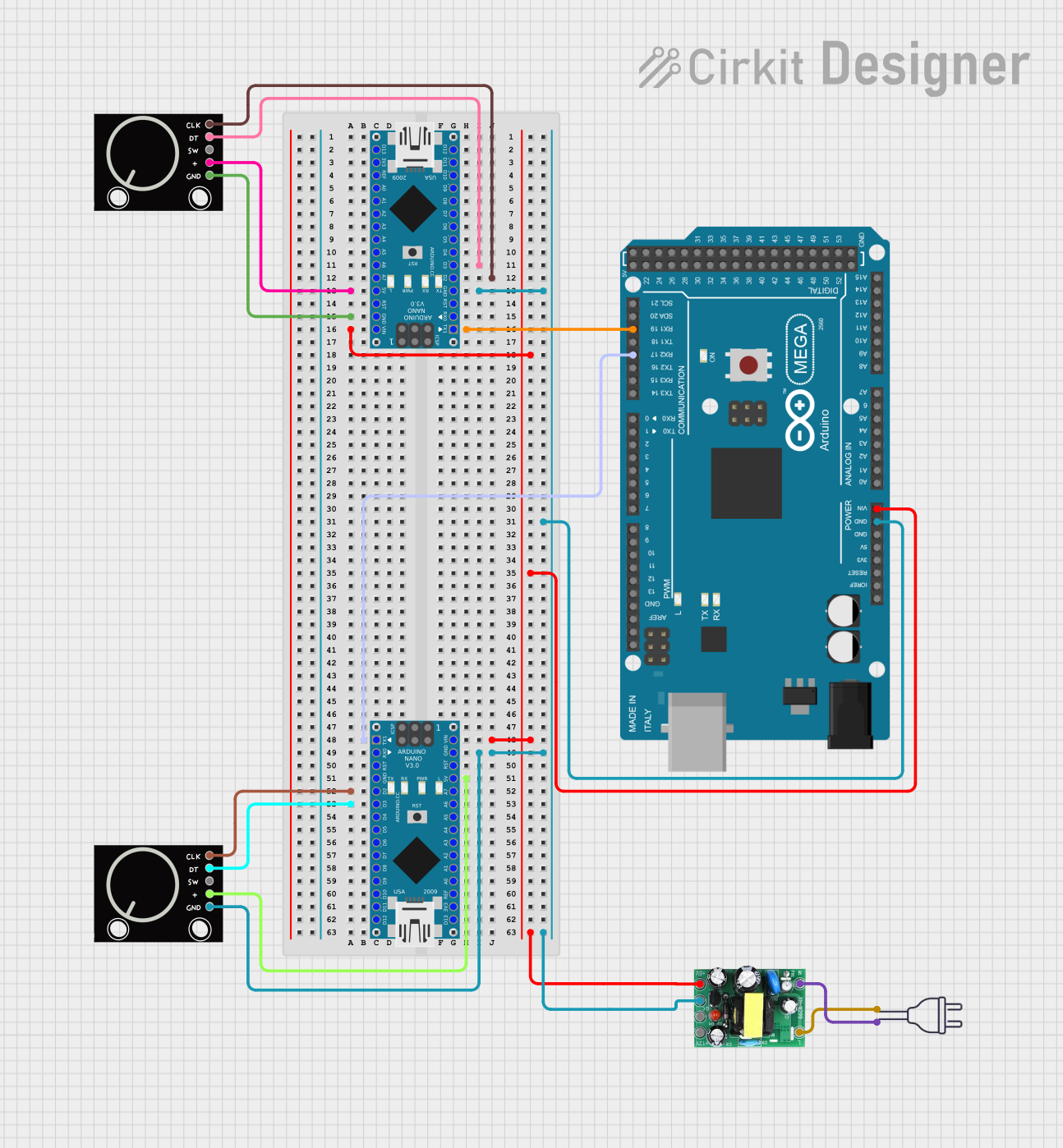
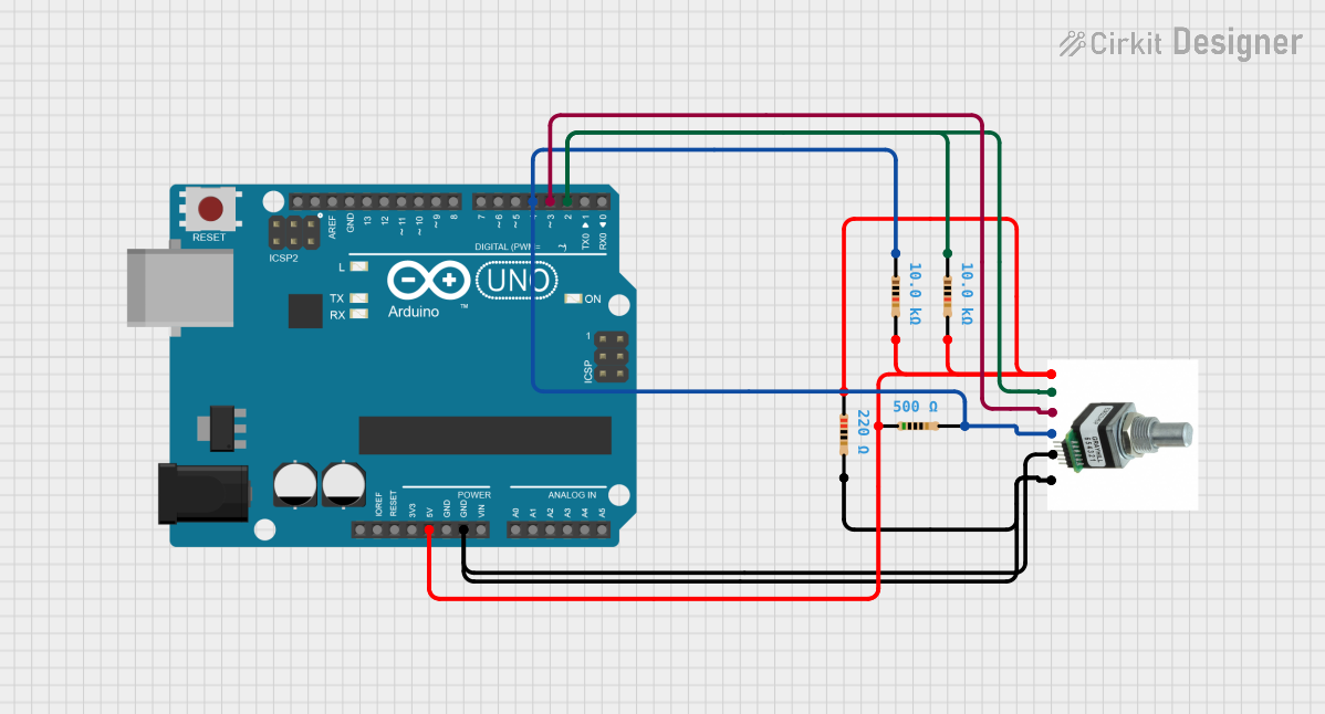

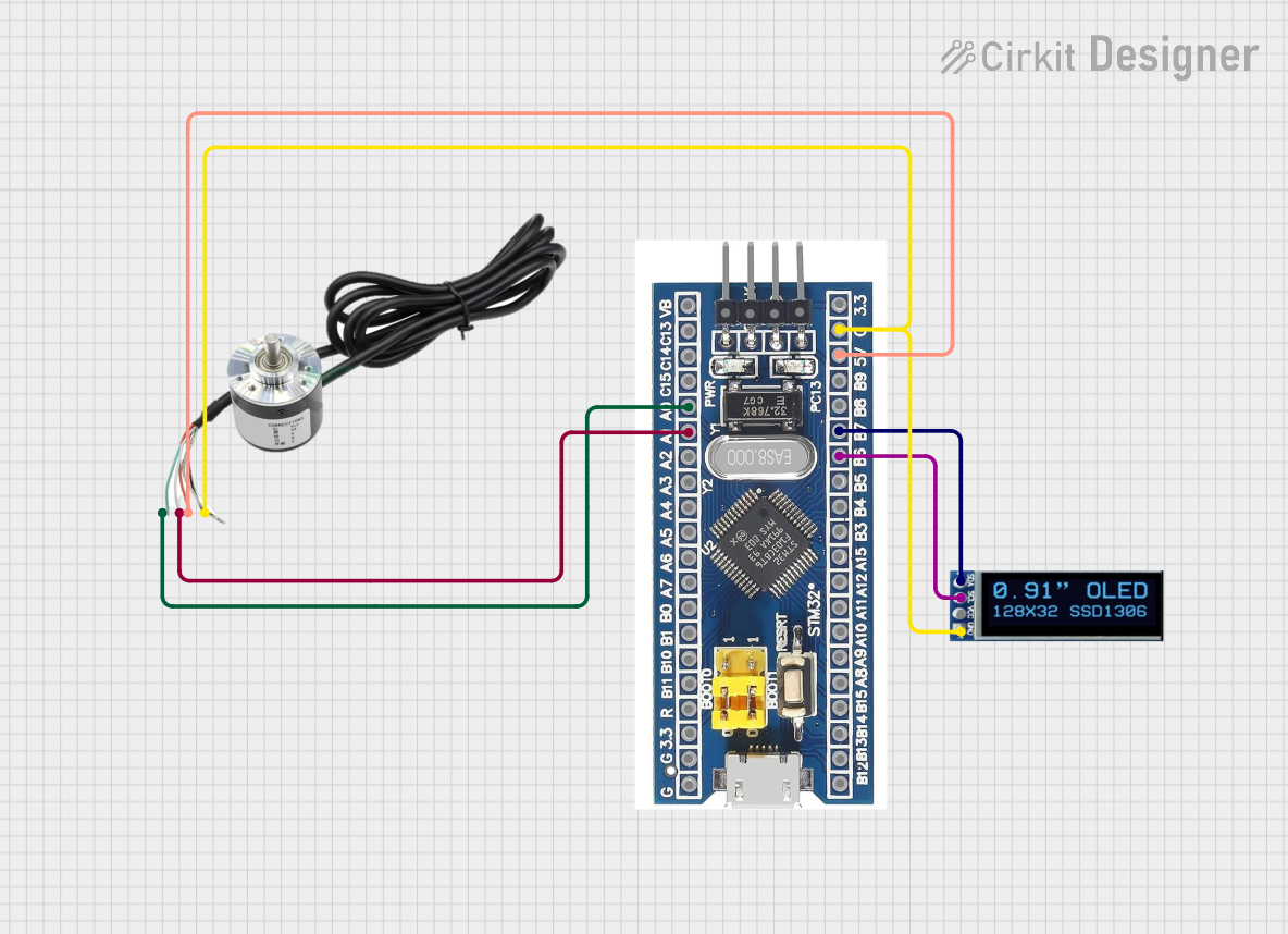
Explore Projects Built with EC11 Rotary Encoder
Common Applications
- Audio equipment (e.g., volume and tone controls)
- User interface navigation (e.g., menu selection in appliances)
- Robotics (e.g., position and speed sensing)
- Industrial control systems
- Gaming devices (e.g., rotary input for controllers)
Technical Specifications
Key Technical Details
- Model: EC11 Rotary Encoder
- Type: Incremental rotary encoder
- Operating Voltage: 5V DC (typical)
- Output: Quadrature signal (A and B channels)
- Resolution: 20 pulses per revolution (PPR)
- Switch Type: Push-button (momentary)
- Operating Temperature: -30°C to +70°C
- Shaft Length: 15mm (varies by model)
- Mounting Style: PCB mount with threaded bushing
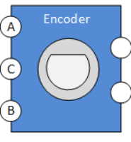
Pin Configuration and Descriptions
The EC11 Rotary Encoder typically has 5 pins: three for the encoder and two for the push-button switch. Below is the pinout:
| Pin Name | Description | Connection |
|---|---|---|
| GND | Ground | Connect to circuit ground |
| VCC | Power supply (5V DC) | Connect to 5V source |
| CLK (A) | Channel A output signal | Connect to microcontroller input pin |
| DT (B) | Channel B output signal | Connect to microcontroller input pin |
| SW | Push-button switch output | Connect to microcontroller input pin (with pull-up resistor) |
Usage Instructions
How to Use the EC11 Rotary Encoder in a Circuit
Wiring the Encoder:
- Connect the GND pin to the ground of your circuit.
- Connect the VCC pin to a 5V DC power source.
- Connect the CLK (A) and DT (B) pins to digital input pins on your microcontroller.
- Connect the SW pin to a digital input pin on your microcontroller, using a pull-up resistor if necessary.
Reading the Encoder:
- The EC11 outputs a quadrature signal on the CLK and DT pins. By monitoring the phase difference between these signals, you can determine the direction of rotation.
- The push-button switch can be used for additional input functionality, such as selecting a menu item.
Debouncing:
- Both the rotary encoder and the push-button switch may produce noisy signals. Use hardware or software debouncing to ensure reliable operation.
Arduino UNO Example Code
Below is an example of how to use the EC11 Rotary Encoder with an Arduino UNO:
// EC11 Rotary Encoder Example Code for Arduino UNO
// Connect CLK to pin 2, DT to pin 3, and SW to pin 4

#define CLK 2  // Channel A (CLK) connected to digital pin 2
#define DT 3   // Channel B (DT) connected to digital pin 3
#define SW 4   // Push-button (SW) connected to digital pin 4

int lastStateCLK;  // To store the previous state of CLK
int currentStateCLK;  // To store the current state of CLK
int counter = 0;  // Counter to track rotation
bool buttonPressed = false;  // To track button press state

void setup() {
  pinMode(CLK, INPUT);
  pinMode(DT, INPUT);
  pinMode(SW, INPUT_PULLUP);  // Use internal pull-up resistor for SW
  Serial.begin(9600);

  // Initialize lastStateCLK with the initial state of CLK
  lastStateCLK = digitalRead(CLK);
}

void loop() {
  // Read the current state of CLK
  currentStateCLK = digitalRead(CLK);

  // Check if the state of CLK has changed
  if (currentStateCLK != lastStateCLK) {
    // Read the state of DT to determine rotation direction
    if (digitalRead(DT) != currentStateCLK) {
      counter++;  // Clockwise rotation
    } else {
      counter--;  // Counterclockwise rotation
    }

    // Print the counter value to the Serial Monitor
    Serial.print("Counter: ");
    Serial.println(counter);
  }

  // Update lastStateCLK to the current state
  lastStateCLK = currentStateCLK;

  // Check if the push-button is pressed
  if (digitalRead(SW) == LOW) {
    if (!buttonPressed) {
      Serial.println("Button Pressed!");
      buttonPressed = true;
    }
  } else {
    buttonPressed = false;
  }
}
Important Considerations and Best Practices
- Debouncing: Use software or hardware debouncing to filter out noise from the encoder and switch signals.
- Pull-up Resistors: Ensure the SW pin is connected to a pull-up resistor (internal or external) to avoid floating states.
- Power Supply: Operate the encoder within its specified voltage range (typically 5V DC).
- Mechanical Limitations: Avoid applying excessive force to the shaft to prevent damage.
Troubleshooting and FAQs
Common Issues and Solutions
No Response from the Encoder:
- Cause: Incorrect wiring or loose connections.
- Solution: Double-check all connections and ensure proper wiring as per the pinout table.
Erratic or Noisy Signals:
- Cause: Signal noise or lack of debouncing.
- Solution: Implement software or hardware debouncing to filter out noise.
Push-Button Not Working:
- Cause: Missing pull-up resistor or incorrect pin configuration.
- Solution: Use an internal or external pull-up resistor and verify the SW pin connection.
Incorrect Direction Detection:
- Cause: Swapped CLK and DT connections.
- Solution: Swap the CLK and DT connections and test again.
FAQs
Q: Can the EC11 Rotary Encoder detect absolute position?
A: No, the EC11 is an incremental encoder and only detects relative position changes. It does not provide absolute position information.
Q: How do I increase the resolution of the encoder?
A: The resolution is fixed at 20 pulses per revolution (PPR). However, you can use software to detect both rising and falling edges of the signals to effectively double the resolution.
Q: Can I use the EC11 with a 3.3V microcontroller?
A: Yes, but ensure the encoder operates reliably at 3.3V. If not, consider using a level shifter or a 5V power source.
Q: Is the EC11 suitable for high-speed applications?
A: The EC11 is designed for low-speed, manual input applications. For high-speed applications, consider using an optical or magnetic encoder.