How to Use Pushbutton START: Examples, Pinouts, and Specs
Introduction
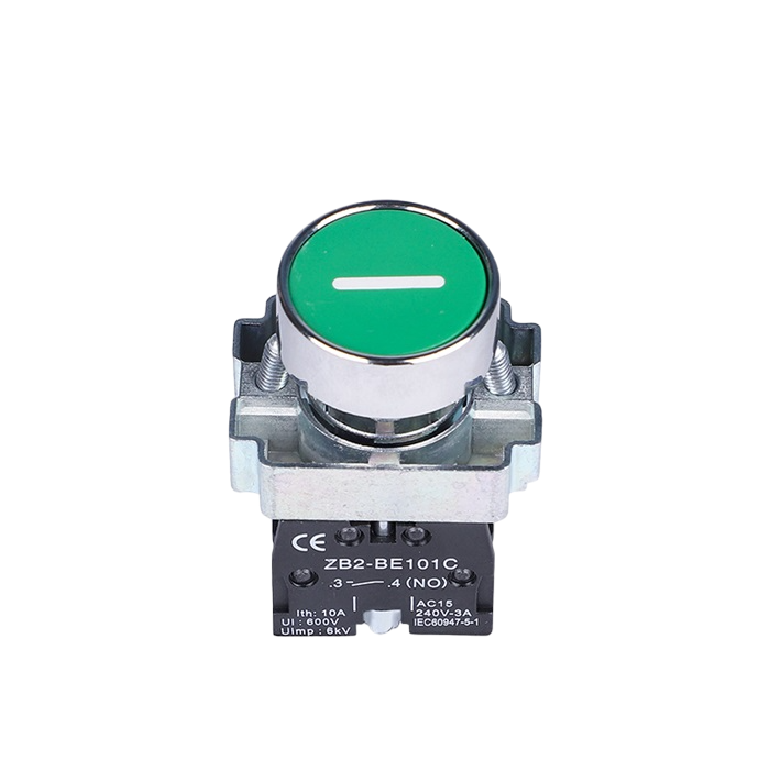
A pushbutton, often referred to as a push-button switch or simply a button, is a fundamental electronic component that allows users to interact with a circuit. The Pushbutton START is a momentary switch that completes an electrical connection when pressed and breaks the connection when released. This type of pushbutton is commonly used to initiate an action, such as starting a machine, triggering a process, or as an input device for user interfaces.
Explore Projects Built with Pushbutton START

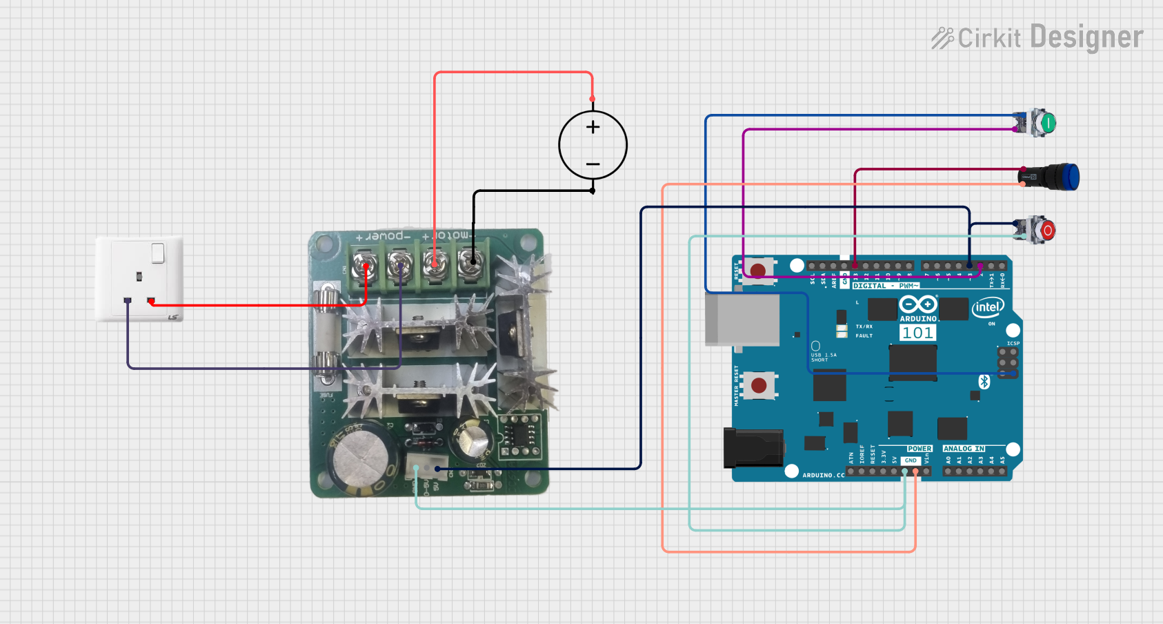
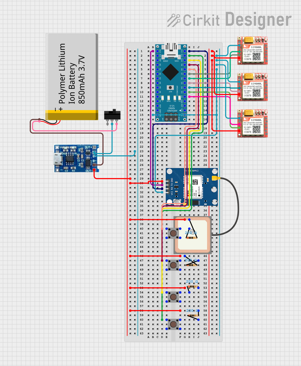

Explore Projects Built with Pushbutton START
Common Applications and Use Cases
- Initiating a process, such as starting an engine or a computer.
- User input for interactive projects.
- As a reset button in electronic devices.
- Debounce logic in digital systems.
- Prototyping and educational projects, often interfaced with microcontrollers like Arduino.
Technical Specifications
Key Technical Details
- Voltage Rating: 3.3V to 5V (suitable for TTL and CMOS logic levels)
- Current Rating: Typically 10mA to 50mA
- Contact Type: Normally open (NO)
- Bounce Time: Approximately 5ms to 20ms
- Durability: Rated for 100,000 to 1,000,000 cycles
Pin Configuration and Descriptions
| Pin Number | Description |
|---|---|
| 1 | Normally Open (NO) |
| 2 | Common (COM) |
Usage Instructions
How to Use the Pushbutton in a Circuit
- Identify the Pins: Locate the Normally Open (NO) and Common (COM) pins on the pushbutton.
- Circuit Integration: Connect the COM pin to one of the power supply rails (either VCC or GND).
- Pull-up/Pull-down Resistor: Attach a pull-up or pull-down resistor to the NO pin to ensure a stable signal when the button is not pressed.
- Signal Connection: Connect the NO pin to the input pin of a microcontroller or another part of the circuit that requires user input.
- Debounce: Implement a debounce mechanism in hardware or software to prevent false triggering due to mechanical bounce.
Important Considerations and Best Practices
- Debouncing: Always use debouncing techniques to ensure reliable operation.
- Current Limiting: Do not exceed the current rating of the pushbutton to avoid damage.
- Mounting: Secure the pushbutton firmly to prevent movement during operation.
- Contact Cleaning: Periodically clean the contacts if used in a dusty environment to maintain performance.
Example Code for Arduino UNO
// Define the pin connected to the pushbutton
const int buttonPin = 2;

// Variable for reading the pushbutton status
int buttonState = 0;

void setup() {
  // Initialize the pushbutton pin as an input with an internal pull-up resistor
  pinMode(buttonPin, INPUT_PULLUP);
}

void loop() {
  // Read the state of the pushbutton value
  buttonState = digitalRead(buttonPin);

  // Check if the pushbutton is pressed
  // If it is, the buttonState is LOW (because of the pull-up resistor)
  if (buttonState == LOW) {
    // Do something when the button is pressed
    // ...
  }
}
Troubleshooting and FAQs
Common Issues
- Button does not respond: Ensure the button is correctly wired and the pull-up/pull-down resistor is in place.
- Intermittent or multiple inputs: This is likely due to bounce. Implement a debounce algorithm in your code.
- Button stuck in pressed state: Check for physical obstructions or damage to the button mechanism.
Solutions and Tips for Troubleshooting
- Debounce Code: Implement a simple debounce algorithm or use libraries available for your platform.
- Check Connections: Verify all connections are secure and the button is not damaged.
- Resistor Value: Use a 10kΩ resistor for pull-up/pull-down to ensure proper voltage levels.
FAQs
Q: Can I use the pushbutton without a pull-up or pull-down resistor? A: It is not recommended as it can lead to undefined behavior due to floating inputs.
Q: How do I know if my pushbutton is damaged? A: A continuity test with a multimeter when the button is pressed and released can determine if the switch is functioning correctly.
Q: Can I use the pushbutton with higher voltages? A: Exceeding the voltage rating can damage the pushbutton. Use a relay or a transistor to control higher voltage circuits.