
How to Use XL4015: Examples, Pinouts, and Specs
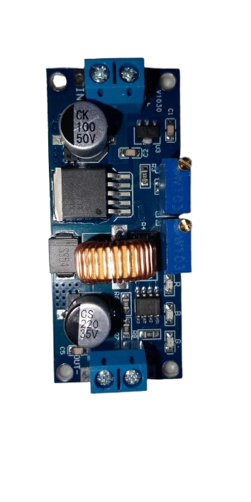
 Design with XL4015 in Cirkit Designer
Introduction
The XL4015 is a step-down (buck) DC-DC converter designed to efficiently convert a higher input voltage to a lower output voltage. It is capable of delivering up to 5A of output current and features an adjustable output voltage, making it a versatile choice for a wide range of power supply applications. The XL4015 is commonly used in battery chargers, LED drivers, and regulated power supplies for electronic devices.
Explore Projects Built with XL4015
 Open Project in Cirkit Designer
 Open Project in Cirkit Designer
 Open Project in Cirkit Designer
 Open Project in Cirkit Designer
Explore Projects Built with XL4015
Open Project in Cirkit DesignerOpen Project in Cirkit DesignerOpen Project in Cirkit DesignerOpen Project in Cirkit DesignerCommon Applications
- Battery charging circuits
- LED lighting systems
- Adjustable power supplies
- Voltage regulation for microcontrollers and other electronics
- Solar power systems
Technical Specifications
The XL4015 is a robust and efficient DC-DC converter with the following key specifications:
| Parameter | Value |
|---|---|
| Input Voltage Range | 4V to 38V |
| Output Voltage Range | 1.25V to 36V (adjustable via potentiometer) |
| Maximum Output Current | 5A |
| Switching Frequency | 180 kHz |
| Efficiency | Up to 96% |
| Output Ripple | ≤ 30mV |
| Operating Temperature | -40°C to +85°C |
| Dimensions | 51mm x 26mm x 14mm |
Pin Configuration and Descriptions
The XL4015 module typically has the following pin layout:
| Pin Name | Description |
|---|---|
| VIN | Input voltage pin. Connect the higher input voltage (4V to 38V). |
| VOUT | Output voltage pin. Provides the regulated lower voltage (1.25V to 36V). |
| GND | Ground pin. Common ground for input and output. |
| EN (optional) | Enable pin. Used to enable or disable the module (active high). |
Usage Instructions
How to Use the XL4015 in a Circuit
- Connect Input Voltage: Connect the input voltage source (e.g., a battery or power adapter) to the
VINandGNDpins. Ensure the input voltage is within the 4V to 38V range. - Connect Load: Connect the load (e.g., an LED, motor, or microcontroller) to the
VOUTandGNDpins. - Adjust Output Voltage: Use the onboard potentiometer to adjust the output voltage. Turn the potentiometer clockwise to increase the voltage and counterclockwise to decrease it. Use a multimeter to measure the output voltage for precise adjustment.
- Enable the Module: If the module has an
ENpin, ensure it is connected to a high logic level (or left floating if internally pulled high) to enable the module.
Important Considerations
- Heat Dissipation: The XL4015 can handle up to 5A of current, but at higher currents, it may generate significant heat. Use a heatsink or active cooling if necessary.
- Input Voltage: Ensure the input voltage is at least 1.5V higher than the desired output voltage for proper operation.
- Output Ripple: Add a capacitor (e.g., 100µF) across the output terminals to reduce voltage ripple if needed.
- Current Limiting: Avoid exceeding the 5A current limit to prevent damage to the module.
Example: Using XL4015 with Arduino UNO
The XL4015 can be used to power an Arduino UNO by stepping down a higher voltage (e.g., 12V) to 5V. Below is an example circuit and code:
Circuit Connections
- Connect a 12V power source to the
VINandGNDpins of the XL4015. - Adjust the output voltage to 5V using the potentiometer.
- Connect the
VOUTpin of the XL4015 to the 5V pin of the Arduino UNO. - Connect the
GNDpin of the XL4015 to the GND pin of the Arduino UNO.
Example Code
// Example code to blink an LED using Arduino UNO powered by XL4015
// Ensure the XL4015 output is set to 5V before connecting to the Arduino

const int ledPin = 13; // Built-in LED pin on Arduino UNO

void setup() {
  pinMode(ledPin, OUTPUT); // Set LED pin as output
}

void loop() {
  digitalWrite(ledPin, HIGH); // Turn the LED on
  delay(1000);               // Wait for 1 second
  digitalWrite(ledPin, LOW);  // Turn the LED off
  delay(1000);               // Wait for 1 second
}
Troubleshooting and FAQs
Common Issues and Solutions
No Output Voltage
- Cause: Input voltage is not connected or is below 4V.
- Solution: Verify the input voltage and ensure it is within the 4V to 38V range.
Output Voltage Not Adjustable
- Cause: Faulty potentiometer or incorrect adjustment.
- Solution: Check the potentiometer for damage and adjust it carefully while monitoring the output voltage with a multimeter.
Excessive Heat
- Cause: High output current or insufficient cooling.
- Solution: Add a heatsink or active cooling to the module. Reduce the load current if possible.
High Output Ripple
- Cause: Insufficient output filtering.
- Solution: Add a capacitor (e.g., 100µF or higher) across the output terminals to reduce ripple.
FAQs
Can the XL4015 be used to charge batteries? Yes, the XL4015 can be used for battery charging applications. However, ensure proper current limiting and voltage adjustment based on the battery type.
What happens if the input voltage exceeds 38V? Exceeding 38V can damage the module. Always ensure the input voltage stays within the specified range.
Can the XL4015 power a Raspberry Pi? Yes, the XL4015 can step down a higher voltage (e.g., 12V) to 5V to power a Raspberry Pi. Ensure the output voltage is precisely set to 5V before connecting the Raspberry Pi.
This concludes the documentation for the XL4015.