Cirkit Designer Logo
Cirkit Designer
Your all-in-one circuit design IDE
Home / 
Component Documentation

How to Use GUVA-S12SD: Examples, Pinouts, and Specs

Image of GUVA-S12SD
Cirkit Designer LogoDesign with GUVA-S12SD in Cirkit Designer

Introduction

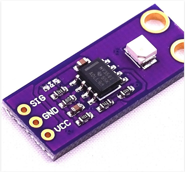
The GUVA-S12SD UV Light Sensor Module is an advanced electronic component designed to detect ultraviolet (UV) radiation. This sensor is capable of measuring the intensity of incident UV light, which is crucial for applications such as weather stations, UV exposure monitoring devices, and scientific research. The module includes a UV photodetector, an amplifier for signal processing, a voltage regulator for stable operation, and a communication interface for easy integration with microcontrollers like the Arduino UNO.

Explore Projects Built with GUVA-S12SD

Use Cirkit Designer to design, explore, and prototype these projects online. Some projects support real-time simulation. Click "Open Project" to start designing instantly!
Cellular-Enabled IoT Device with Real-Time Clock and Power Management
Image of LRCM PHASE 2 BASIC: A project utilizing GUVA-S12SD in a practical application
This circuit features a LilyGo-SIM7000G module for cellular communication and GPS functionality, interfaced with an RTC DS3231 for real-time clock capabilities. It includes voltage sensing through two voltage sensor modules, and uses an 8-channel opto-coupler for isolating different parts of the circuit. Power management is handled by a buck converter connected to a DC power source and batteries, with a fuse for protection and a rocker switch for on/off control. Additionally, there's an LED for indication purposes.
Cirkit Designer LogoOpen Project in Cirkit Designer
ESP32-S3 Battery-Powered Environmental Monitoring System with OLED Display
Image of Diagram wiring: A project utilizing GUVA-S12SD in a practical application
This circuit is a sensor and display system powered by a UPS module with a 12V power supply and 18650 batteries. It includes an ESP32 microcontroller that interfaces with various sensors (DHT22, Strain Gauge, MPU-6050, ADXL345) and an OLED display, with power regulation provided by a step-down buck converter.
Cirkit Designer LogoOpen Project in Cirkit Designer
ESP32-S3 Based Vibration Detection System with TFT Display and Power Backup
Image of IOT Thesis: A project utilizing GUVA-S12SD in a practical application
This circuit features an ESP32-S3 microcontroller connected to various peripherals including an ADXL355 accelerometer, an SW-420 vibration sensor, a buzzer module, and an ILI9341 TFT display. The ESP32-S3 manages sensor inputs and provides output to the display and buzzer. Power management is handled by a 12V to 5V step-down converter, and a UPS ensures uninterrupted power supply, with a rocker switch to control the power flow.
Cirkit Designer LogoOpen Project in Cirkit Designer
Solar-Powered Environmental Monitoring System with ESP32-C3 and MPPT Charge Control
Image of Gen Shed Xiao ESP32C3 INA3221 AHT21 -1: A project utilizing GUVA-S12SD in a practical application
This circuit is designed for solar energy management and monitoring. It includes a 12V AGM battery charged by solar panels through an MPPT charge controller, with voltage monitoring provided by an INA3221 sensor. Additionally, a 3.7V battery is connected to an ESP32-C3 microcontroller and an AHT21 sensor for environmental data collection, with power management handled by a Waveshare Solar Manager.
Cirkit Designer LogoOpen Project in Cirkit Designer

Explore Projects Built with GUVA-S12SD

Use Cirkit Designer to design, explore, and prototype these projects online. Some projects support real-time simulation. Click "Open Project" to start designing instantly!
Image of LRCM PHASE 2 BASIC: A project utilizing GUVA-S12SD in a practical application
Cellular-Enabled IoT Device with Real-Time Clock and Power Management
This circuit features a LilyGo-SIM7000G module for cellular communication and GPS functionality, interfaced with an RTC DS3231 for real-time clock capabilities. It includes voltage sensing through two voltage sensor modules, and uses an 8-channel opto-coupler for isolating different parts of the circuit. Power management is handled by a buck converter connected to a DC power source and batteries, with a fuse for protection and a rocker switch for on/off control. Additionally, there's an LED for indication purposes.
Cirkit Designer LogoOpen Project in Cirkit Designer
Image of Diagram wiring: A project utilizing GUVA-S12SD in a practical application
ESP32-S3 Battery-Powered Environmental Monitoring System with OLED Display
This circuit is a sensor and display system powered by a UPS module with a 12V power supply and 18650 batteries. It includes an ESP32 microcontroller that interfaces with various sensors (DHT22, Strain Gauge, MPU-6050, ADXL345) and an OLED display, with power regulation provided by a step-down buck converter.
Cirkit Designer LogoOpen Project in Cirkit Designer
Image of IOT Thesis: A project utilizing GUVA-S12SD in a practical application
ESP32-S3 Based Vibration Detection System with TFT Display and Power Backup
This circuit features an ESP32-S3 microcontroller connected to various peripherals including an ADXL355 accelerometer, an SW-420 vibration sensor, a buzzer module, and an ILI9341 TFT display. The ESP32-S3 manages sensor inputs and provides output to the display and buzzer. Power management is handled by a 12V to 5V step-down converter, and a UPS ensures uninterrupted power supply, with a rocker switch to control the power flow.
Cirkit Designer LogoOpen Project in Cirkit Designer
Image of Gen Shed Xiao ESP32C3 INA3221 AHT21 -1: A project utilizing GUVA-S12SD in a practical application
Solar-Powered Environmental Monitoring System with ESP32-C3 and MPPT Charge Control
This circuit is designed for solar energy management and monitoring. It includes a 12V AGM battery charged by solar panels through an MPPT charge controller, with voltage monitoring provided by an INA3221 sensor. Additionally, a 3.7V battery is connected to an ESP32-C3 microcontroller and an AHT21 sensor for environmental data collection, with power management handled by a Waveshare Solar Manager.
Cirkit Designer LogoOpen Project in Cirkit Designer

Common Applications and Use Cases

  • Monitoring UV index for weather stations
  • UV exposure assessment for health and safety devices
  • Scientific experiments involving UV light measurement
  • Industrial process control where UV light is a factor

Technical Specifications

Key Technical Details

  • Spectral Range: 200nm to 370nm
  • Responsivity: 0.1 to 1.0
  • Operating Voltage: 2.5V to 5.5V
  • Output Voltage: 0V to 1V (linear relationship with UV intensity)
  • Response Time: Less than 1 second
  • Operating Temperature: -20°C to +85°C

Pin Configuration and Descriptions

Pin Number Name Description
1 VCC Power supply (2.5V to 5.5V)
2 GND Ground connection
3 OUT Analog output voltage

Usage Instructions

How to Use the Component in a Circuit

  1. Power Supply: Connect the VCC pin to a power source between 2.5V and 5.5V.
  2. Ground: Connect the GND pin to the ground of your circuit.
  3. Signal Output: Connect the OUT pin to an analog input pin on your microcontroller to read the UV intensity levels.

Important Considerations and Best Practices

  • Avoid exposing the sensor to direct sunlight for extended periods to prevent damage.
  • Use a shield or cover to protect the sensor from physical damage and dust.
  • Calibrate the sensor for your specific application to ensure accurate readings.
  • Implement a smoothing algorithm in your code to deal with signal noise and fluctuations.

Example Code for Arduino UNO

// Define the analog pin connected to the sensor output
const int uvSensorPin = A0;

void setup() {
  // Initialize serial communication at 9600 baud rate
  Serial.begin(9600);
}

void loop() {
  // Read the analog value from the sensor
  int uvLevel = analogRead(uvSensorPin);
  
  // Convert the analog value to a voltage level
  float voltage = uvLevel * (5.0 / 1023.0);
  
  // Print the voltage level to the Serial Monitor
  Serial.print("UV Sensor Voltage: ");
  Serial.println(voltage);
  
  // Delay for a second before the next reading
  delay(1000);
}

Troubleshooting and FAQs

Common Issues Users Might Face

  • Inaccurate Readings: Ensure the sensor is properly calibrated and not exposed to direct sunlight for prolonged periods.
  • No Output: Check the power supply and connections to the sensor. Ensure the OUT pin is connected to an analog input on the microcontroller.
  • Fluctuating Readings: Implement a software filter or averaging algorithm to stabilize the readings.

Solutions and Tips for Troubleshooting

  • Calibration: Use a known UV light source to calibrate the sensor's output against the UV index.
  • Connections: Double-check all connections, including solder joints, for any loose or broken connections.
  • Code Debugging: Verify that the code is correctly reading the analog pin and that the serial communication is properly set up.

FAQs

Q: Can the GUVA-S12SD sensor detect visible light? A: No, the sensor is designed to detect UV light and has a spectral range of 200nm to 370nm, which is outside the visible spectrum.

Q: How do I convert the voltage reading to UV index? A: You will need to calibrate the sensor with a known UV light source and establish a relationship between the voltage output and the UV index for your specific application.

Q: Is the sensor waterproof? A: The GUVA-S12SD is not inherently waterproof. It should be housed in a protective enclosure if used in moist or outdoor environments.

Q: What is the lifespan of the sensor? A: The lifespan can vary based on usage, but with proper care and protection from overexposure to UV light, the sensor can last for several years.

For further assistance or technical support, please contact the manufacturer or your local distributor.