How to Use BNO055: Examples, Pinouts, and Specs
Introduction
The BNO055 is a 9-axis absolute orientation sensor developed by Adafruit. It integrates a 3-axis accelerometer, a 3-axis gyroscope, and a 3-axis magnetometer into a single package. Unlike traditional sensors, the BNO055 features an onboard microcontroller that fuses raw sensor data to provide accurate orientation information in the form of Euler angles or quaternions. This eliminates the need for complex sensor fusion algorithms on the host microcontroller.
Explore Projects Built with BNO055

Explore Projects Built with BNO055
Common Applications and Use Cases
- Robotics for precise motion tracking and navigation
- Drones for stable flight and orientation control
- Virtual reality (VR) and augmented reality (AR) systems
- Wearable devices for activity tracking
- Industrial automation and human-machine interfaces
Technical Specifications
The BNO055 is a highly versatile sensor with the following key specifications:
| Parameter | Value |
|---|---|
| Operating Voltage | 3.3V to 5V |
| Communication Interfaces | I²C, UART |
| Power Consumption | ~12mA (typical) |
| Accelerometer Range | ±2g, ±4g, ±8g, ±16g |
| Gyroscope Range | ±125°/s, ±250°/s, ±500°/s, ±2000°/s |
| Magnetometer Range | ±1300µT |
| Output Data Formats | Euler angles, quaternions, linear acceleration, gravity vector |
| Operating Temperature Range | -40°C to +85°C |
| Dimensions | 20mm x 22mm x 3.5mm |
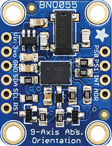
Pin Configuration and Descriptions
The BNO055 breakout board from Adafruit has the following pin layout:
| Pin Name | Description |
|---|---|
| VIN | Power input (3.3V to 5V) |
| GND | Ground connection |
| SDA | I²C data line |
| SCL | I²C clock line |
| PS0 | Protocol selection pin (set to LOW for I²C, HIGH for UART) |
| PS1 | Protocol selection pin (set to LOW for I²C, HIGH for UART) |
| RST | Reset pin (active LOW) |
| INT | Interrupt pin (optional, used for advanced features) |
| TX | UART transmit line (used when UART protocol is selected) |
| RX | UART receive line (used when UART protocol is selected) |
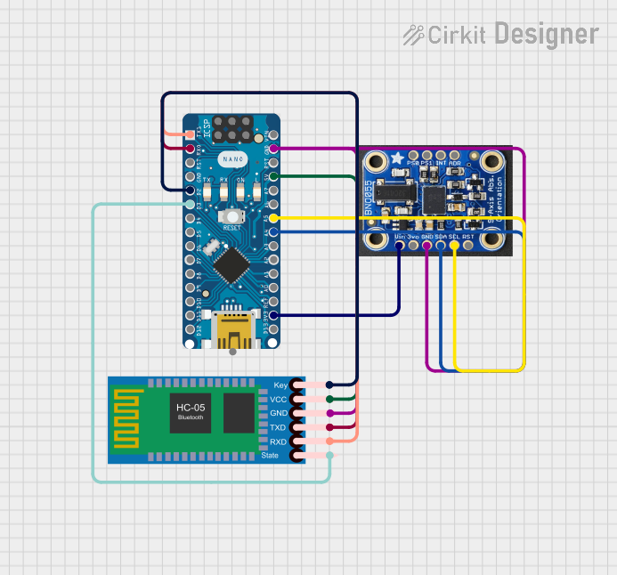
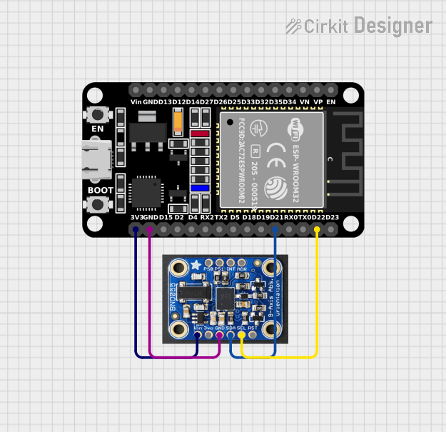
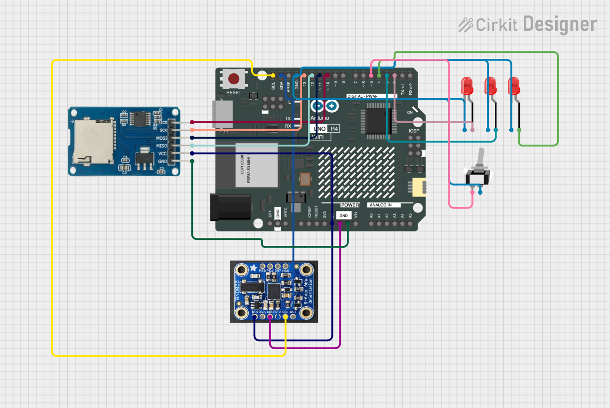
Usage Instructions
How to Use the BNO055 in a Circuit
- Power the Sensor: Connect the VIN pin to a 3.3V or 5V power source and the GND pin to ground.
- Select Communication Protocol:
- For I²C: Connect the PS0 and PS1 pins to GND.
- For UART: Connect the PS0 and PS1 pins to VIN.
- Connect Communication Lines:
- For I²C: Connect the SDA and SCL pins to the corresponding I²C pins on your microcontroller.
- For UART: Connect the TX and RX pins to the UART pins on your microcontroller.
- Install Required Libraries: If using an Arduino, install the Adafruit BNO055 library via the Arduino Library Manager.
- Write Code: Use the library functions to initialize the sensor, configure settings, and read orientation data.
Important Considerations and Best Practices
- I²C Pull-Up Resistors: Ensure that the I²C lines (SDA and SCL) have appropriate pull-up resistors (typically 4.7kΩ).
- Mounting Orientation: Mount the sensor securely and ensure it is aligned with the axes of your system for accurate readings.
- Calibration: Perform the sensor's built-in calibration routine for optimal accuracy. This includes accelerometer, gyroscope, and magnetometer calibration.
- Avoid Magnetic Interference: Keep the sensor away from strong magnetic fields, which can affect the magnetometer's accuracy.
Example Code for Arduino UNO
Below is an example of how to use the BNO055 with an Arduino UNO via I²C:
#include <Wire.h>
#include <Adafruit_Sensor.h>
#include <Adafruit_BNO055.h>

// Create an instance of the BNO055 sensor
Adafruit_BNO055 bno = Adafruit_BNO055(55);

void setup() {
  Serial.begin(9600);
  // Initialize the BNO055 sensor
  if (!bno.begin()) {
    Serial.println("Error: BNO055 not detected. Check connections.");
    while (1);
  }
  Serial.println("BNO055 initialized successfully!");

  // Set the sensor to NDOF mode (sensor fusion mode)
  bno.setMode(Adafruit_BNO055::OPERATION_MODE_NDOF);

  // Allow time for the sensor to stabilize
  delay(1000);
}

void loop() {
  // Get orientation data (Euler angles)
  sensors_event_t event;
  bno.getEvent(&event);

  // Print orientation data to the Serial Monitor
  Serial.print("Heading: ");
  Serial.print(event.orientation.x);
  Serial.print("°, Pitch: ");
  Serial.print(event.orientation.y);
  Serial.print("°, Roll: ");
  Serial.print(event.orientation.z);
  Serial.println("°");

  delay(500); // Delay for readability
}
Troubleshooting and FAQs
Common Issues and Solutions
Sensor Not Detected:
- Cause: Incorrect wiring or communication protocol mismatch.
- Solution: Double-check the connections and ensure the PS0 and PS1 pins are set correctly for the desired protocol.
Inaccurate Readings:
- Cause: Sensor not calibrated or exposed to magnetic interference.
- Solution: Perform the calibration routine and keep the sensor away from magnetic sources.
No Data Output:
- Cause: Incorrect library installation or initialization failure.
- Solution: Ensure the Adafruit BNO055 library is installed and the sensor is initialized properly in the code.
Random Freezing or Crashes:
- Cause: Insufficient power supply or unstable connections.
- Solution: Use a stable power source and check all connections for reliability.
FAQs
Q: Can the BNO055 be used with 5V logic microcontrollers?
A: Yes, the BNO055 breakout board includes level-shifting circuitry, making it compatible with both 3.3V and 5V logic.
Q: How do I perform calibration?
A: The Adafruit library includes functions to check calibration status and guide you through the calibration process. Follow the library's examples for detailed instructions.
Q: What is the maximum I²C clock speed supported?
A: The BNO055 supports I²C clock speeds up to 400kHz (Fast Mode).
Q: Can I use the BNO055 for GPS-based navigation?
A: The BNO055 does not include GPS functionality, but it can complement GPS modules by providing orientation and motion data.