How to Use solar lamp control board: Examples, Pinouts, and Specs
Introduction
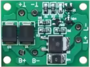
The Solar Lamp Control Board is a specialized circuit board designed to manage the operation of solar-powered lamps. It integrates key functionalities such as charging the battery from a solar panel, controlling the light output (e.g., turning the lamp on/off or dimming), and optimizing power efficiency to ensure reliable and long-lasting performance. This component is essential for solar lighting systems, enabling them to operate autonomously and efficiently.
Explore Projects Built with solar lamp control board
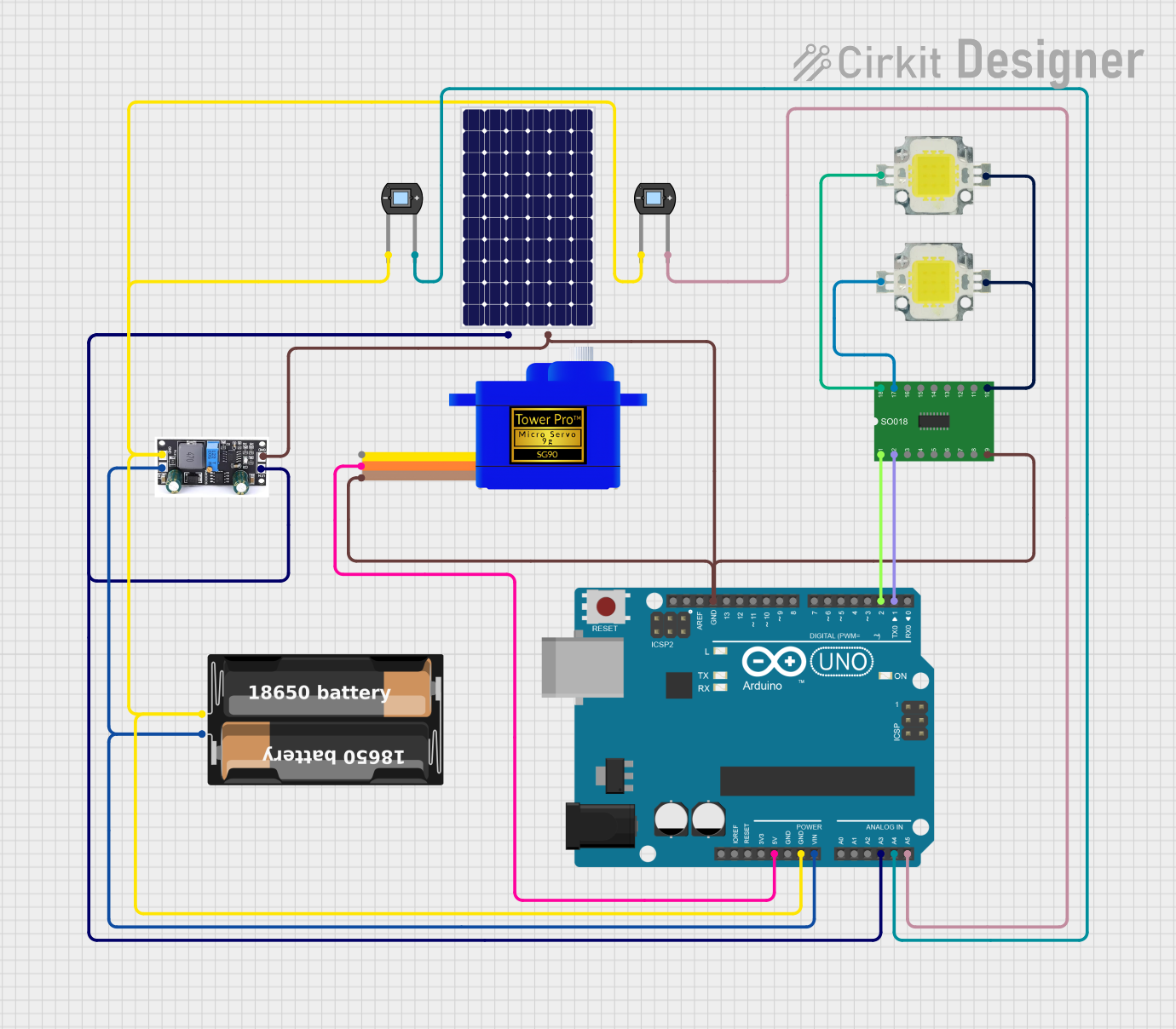
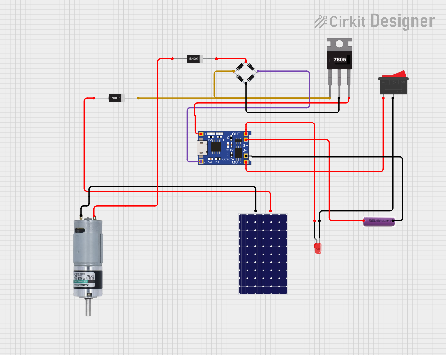
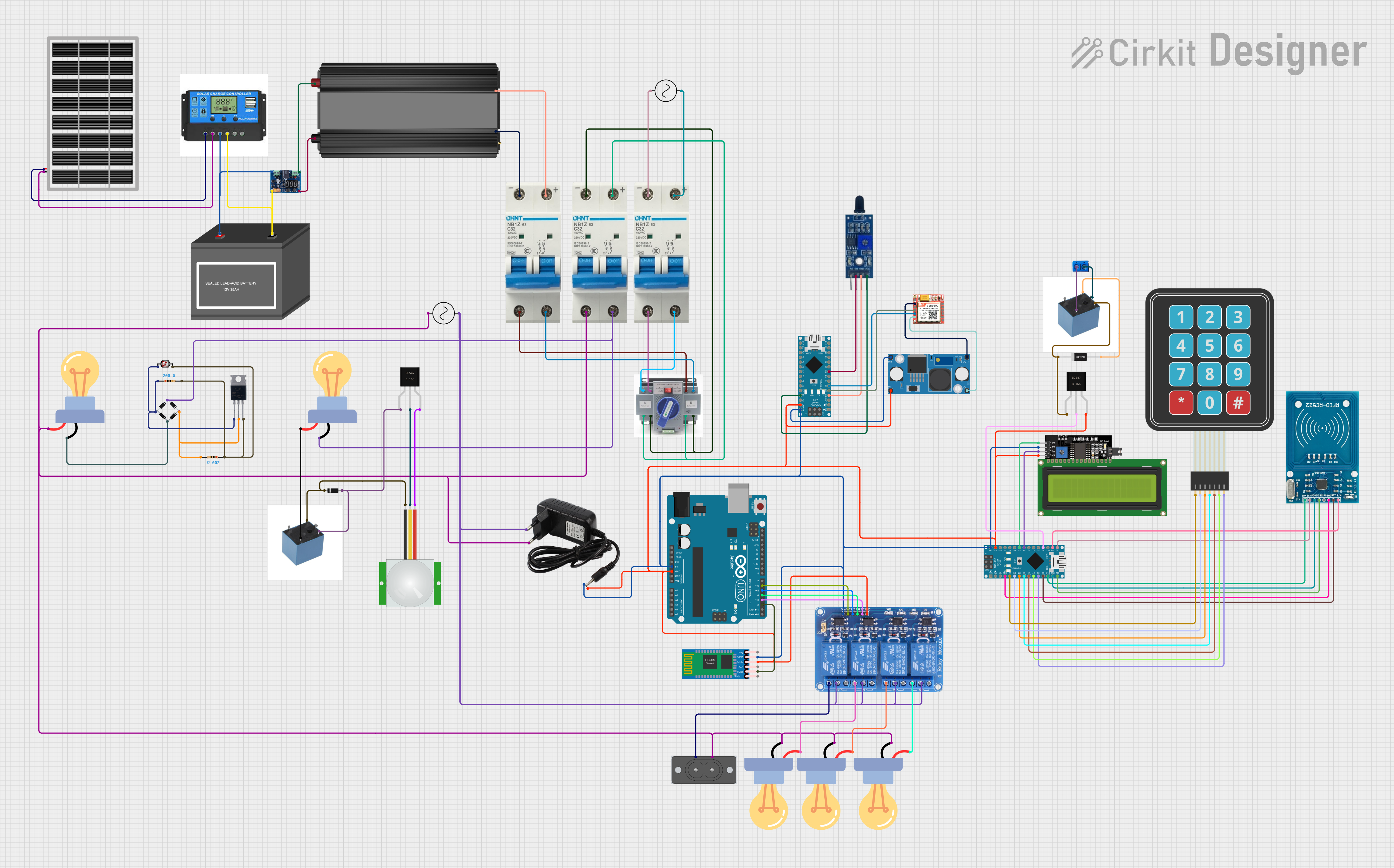

Explore Projects Built with solar lamp control board
Common Applications and Use Cases
- Solar garden lights
- Streetlights powered by solar energy
- Portable solar lanterns
- Off-grid lighting systems
- Emergency lighting solutions
Technical Specifications
Below are the key technical details and pin configuration for the Solar Lamp Control Board:
Key Technical Details
| Parameter | Value |
|---|---|
| Input Voltage Range | 5V to 18V (from solar panel) |
| Battery Type Supported | Lithium-ion (3.7V nominal) |
| Maximum Charging Current | 1A |
| Load Output Voltage | 3.3V or 5V (regulated) |
| Maximum Load Current | 1.5A |
| Efficiency | Up to 90% (depending on load) |
| Operating Temperature Range | -20°C to 60°C |
| Protection Features | Overcharge, over-discharge, and |
| short-circuit protection |
Pin Configuration and Descriptions
| Pin Name | Description |
|---|---|
| VIN | Input voltage from the solar panel (5V to 18V). |
| BAT+ | Positive terminal for the rechargeable battery. |
| BAT- | Negative terminal for the rechargeable battery. |
| LOAD+ | Positive terminal for the load (e.g., LED lamp). |
| LOAD- | Negative terminal for the load. |
| GND | Ground connection for the circuit. |
| LED_CTRL | Control pin for dimming or toggling the LED output (optional, PWM capable). |
Usage Instructions
How to Use the Component in a Circuit
- Connect the Solar Panel: Attach the positive and negative terminals of the solar panel to the
VINandGNDpins, respectively. Ensure the solar panel's voltage is within the supported range (5V to 18V). - Connect the Battery: Connect the rechargeable lithium-ion battery to the
BAT+andBAT-pins. Ensure the battery is compatible with the board's specifications. - Connect the Load: Attach the LED lamp or other load to the
LOAD+andLOAD-pins. Ensure the load does not exceed the maximum current rating (1.5A). - Optional Control: If dimming or toggling the LED is required, connect a microcontroller (e.g., Arduino) to the
LED_CTRLpin. This pin supports PWM signals for brightness control.
Important Considerations and Best Practices
- Battery Protection: Ensure the battery has built-in protection circuitry or verify that the control board provides overcharge and over-discharge protection.
- Heat Dissipation: If the load current is high, ensure proper ventilation or heat sinking to prevent overheating.
- Polarity: Double-check all connections to avoid reverse polarity, which can damage the board.
- Solar Panel Sizing: Use a solar panel with sufficient power output to charge the battery effectively, especially in low-light conditions.
Example: Using with an Arduino UNO
The LED_CTRL pin can be connected to an Arduino UNO for controlling the brightness of the LED lamp. Below is an example code snippet:
// Example code to control the brightness of a solar lamp using PWM
// Connect the LED_CTRL pin of the Solar Lamp Control Board to Arduino pin 9

const int ledControlPin = 9; // Pin connected to LED_CTRL

void setup() {
  pinMode(ledControlPin, OUTPUT); // Set pin 9 as an output
}

void loop() {
  // Gradually increase brightness
  for (int brightness = 0; brightness <= 255; brightness++) {
    analogWrite(ledControlPin, brightness); // Write PWM signal to LED_CTRL
    delay(10); // Small delay for smooth transition
  }

  // Gradually decrease brightness
  for (int brightness = 255; brightness >= 0; brightness--) {
    analogWrite(ledControlPin, brightness); // Write PWM signal to LED_CTRL
    delay(10); // Small delay for smooth transition
  }
}
Troubleshooting and FAQs
Common Issues and Solutions
The lamp does not turn on:
- Check the battery voltage. If it is too low, the board may have triggered over-discharge protection.
- Verify the connections to the
LOAD+andLOAD-pins. - Ensure the solar panel is charging the battery during daylight.
The battery is not charging:
- Confirm that the solar panel's voltage is within the supported range (5V to 18V).
- Check the connections to the
VINandGNDpins. - Inspect the battery for any damage or compatibility issues.
The LED brightness is inconsistent:
- Ensure the load does not exceed the maximum current rating (1.5A).
- If using PWM control, verify the signal from the microcontroller is stable.
The board overheats:
- Reduce the load current or improve ventilation around the board.
- Check for any short circuits in the wiring.
FAQs
Can I use a different type of battery?
The board is designed for lithium-ion batteries. Using other types may require additional circuitry or modifications.What happens if the solar panel voltage exceeds 18V?
Exceeding the voltage range can damage the board. Use a solar panel with a compatible voltage or add a voltage regulator.Can I connect multiple LEDs to the board?
Yes, as long as the total current does not exceed 1.5A. Use LEDs in parallel with appropriate resistors if needed.Is the board waterproof?
No, the board is not waterproof. Use an enclosure to protect it in outdoor applications.