Cirkit Designer Logo
Cirkit Designer
Your all-in-one circuit design IDE
Home / 
Component Documentation

How to Use MOSFET Switch SPDT: Examples, Pinouts, and Specs

Image of MOSFET Switch SPDT
Cirkit Designer LogoDesign with MOSFET Switch SPDT in Cirkit Designer

Introduction

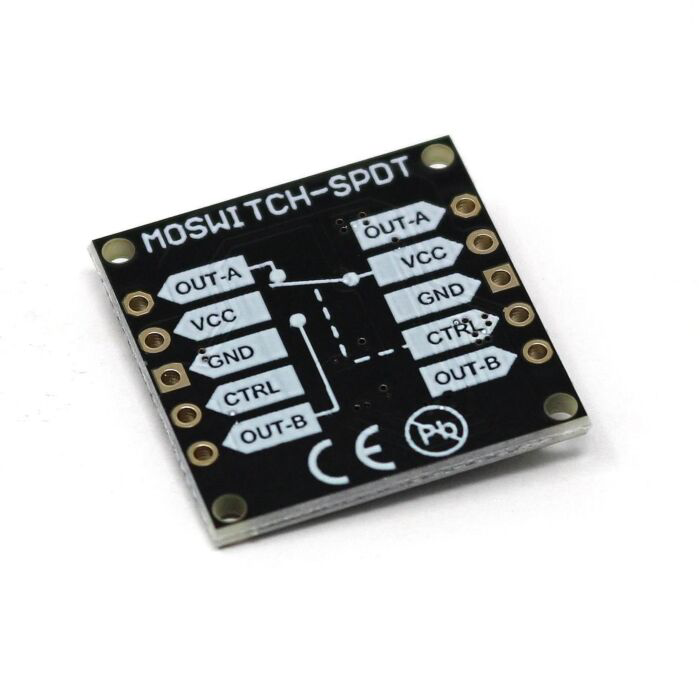
A MOSFET Switch SPDT (Single Pole Double Throw) is an electronic switch that utilizes Metal-Oxide-Semiconductor Field-Effect Transistor (MOSFET) technology to alternate an electrical signal between two distinct paths. This component is essential in applications where control of current flow is required, such as in power supply circuits, motor control, and signal routing.

Explore Projects Built with MOSFET Switch SPDT

Use Cirkit Designer to design, explore, and prototype these projects online. Some projects support real-time simulation. Click "Open Project" to start designing instantly!
9V Battery-Powered DC Motor with Toggle Switch Control
Image of MOTOR BATTERY: A project utilizing MOSFET Switch SPDT in a practical application
This circuit is designed to control a DC motor using a single-pole single-throw (SPST) toggle switch. The 9V battery provides power to the motor, and the toggle switch acts as an on/off control to allow or interrupt the current flow to the motor.
Cirkit Designer LogoOpen Project in Cirkit Designer
SPST Rocker Switch Array Circuit
Image of SWITCH CONNECTION: A project utilizing MOSFET Switch SPDT in a practical application
This circuit features a parallel arrangement of SPST rocker switches, each capable of independently controlling the connection of a separate circuit branch to a common line. It is likely designed for simple on/off control of multiple individual loads or signals, with each switch operating a distinct load or signal path.
Cirkit Designer LogoOpen Project in Cirkit Designer
Raspberry Pi-Controlled LED Lighting System with Time-Based Color Switching
Image of LED aquarium: A project utilizing MOSFET Switch SPDT in a practical application
This circuit consists of a Raspberry Pi 5 microcontroller programmed to control two sets of LEDs (blue and green) via two separate MOSFET switches. The green LEDs are turned on continuously, while the blue LEDs are programmed to turn on only between 18:00 and 22:00 hours. Each LED is connected in series with a resistor to limit the current, and the MOSFETs are controlled by GPIO pins on the Raspberry Pi, with additional resistors connected to the control pins.
Cirkit Designer LogoOpen Project in Cirkit Designer
Solar-Powered DC Motor Control with Battery Backup
Image of External Design SIP Robotics: A project utilizing MOSFET Switch SPDT in a practical application
This circuit features a DC motor powered by a solar panel and a battery, with a toggle switch (SPST) to control the motor's operation. The solar panel and battery are connected in parallel to provide a stable voltage source. The toggle switch allows the user to turn the motor on and off manually.
Cirkit Designer LogoOpen Project in Cirkit Designer

Explore Projects Built with MOSFET Switch SPDT

Use Cirkit Designer to design, explore, and prototype these projects online. Some projects support real-time simulation. Click "Open Project" to start designing instantly!
Image of MOTOR BATTERY: A project utilizing MOSFET Switch SPDT in a practical application
9V Battery-Powered DC Motor with Toggle Switch Control
This circuit is designed to control a DC motor using a single-pole single-throw (SPST) toggle switch. The 9V battery provides power to the motor, and the toggle switch acts as an on/off control to allow or interrupt the current flow to the motor.
Cirkit Designer LogoOpen Project in Cirkit Designer
Image of SWITCH CONNECTION: A project utilizing MOSFET Switch SPDT in a practical application
SPST Rocker Switch Array Circuit
This circuit features a parallel arrangement of SPST rocker switches, each capable of independently controlling the connection of a separate circuit branch to a common line. It is likely designed for simple on/off control of multiple individual loads or signals, with each switch operating a distinct load or signal path.
Cirkit Designer LogoOpen Project in Cirkit Designer
Image of LED aquarium: A project utilizing MOSFET Switch SPDT in a practical application
Raspberry Pi-Controlled LED Lighting System with Time-Based Color Switching
This circuit consists of a Raspberry Pi 5 microcontroller programmed to control two sets of LEDs (blue and green) via two separate MOSFET switches. The green LEDs are turned on continuously, while the blue LEDs are programmed to turn on only between 18:00 and 22:00 hours. Each LED is connected in series with a resistor to limit the current, and the MOSFETs are controlled by GPIO pins on the Raspberry Pi, with additional resistors connected to the control pins.
Cirkit Designer LogoOpen Project in Cirkit Designer
Image of External Design SIP Robotics: A project utilizing MOSFET Switch SPDT in a practical application
Solar-Powered DC Motor Control with Battery Backup
This circuit features a DC motor powered by a solar panel and a battery, with a toggle switch (SPST) to control the motor's operation. The solar panel and battery are connected in parallel to provide a stable voltage source. The toggle switch allows the user to turn the motor on and off manually.
Cirkit Designer LogoOpen Project in Cirkit Designer

Common Applications and Use Cases

  • Power management in electronic devices
  • Switching between two different power sources
  • Controlling the direction of motor rotation
  • Signal routing in audio and RF circuits

Technical Specifications

Key Technical Details

  • Control Voltage (Vgs): 3.3V - 5V (compatible with most microcontrollers including Arduino)
  • Continuous Current Rating: Up to 3A without heat sink
  • Maximum Switching Voltage: 30V
  • On-Resistance (Rds(on)): Typically less than 50 mΩ
  • Switching Speed: Fast switching capable (nanoseconds to microseconds range)

Pin Configuration and Descriptions

Pin Number Name Description
1 IN Control input from microcontroller (3.3V - 5V)
2 V+ Source voltage for the load (up to 30V)
3 NO Normally open terminal, connected to load when IN is high
4 NC Normally closed terminal, connected to load when IN is low
5 GND Ground reference for the control signal and load

Usage Instructions

How to Use the Component in a Circuit

  1. Connect the GND pin to the ground of your power supply and microcontroller.
  2. Connect the V+ pin to the positive terminal of your power supply.
  3. Connect the IN pin to a digital output pin on your microcontroller.
  4. Connect the load you wish to control to either the NO or NC terminal, depending on the desired default state.
  5. Ensure that the control voltage and the load voltage do not exceed the specified limits.

Important Considerations and Best Practices

  • Always verify that the power ratings of the MOSFET Switch do not exceed the specifications.
  • Use a pull-down resistor on the IN pin to ensure the switch remains off when the control signal is not active.
  • Consider using a heat sink if the current through the MOSFET is close to the maximum continuous current rating.
  • Avoid inductive loads without proper flyback diodes to prevent voltage spikes that could damage the MOSFET.

Example Code for Arduino UNO

// Define the control pin for the MOSFET Switch SPDT
const int mosfetControlPin = 7;

void setup() {
  // Set the MOSFET control pin as an output
  pinMode(mosfetControlPin, OUTPUT);
}

void loop() {
  // Turn on the MOSFET switch (connects to NO terminal)
  digitalWrite(mosfetControlPin, HIGH);
  delay(1000); // Wait for 1 second

  // Turn off the MOSFET switch (connects to NC terminal)
  digitalWrite(mosfetControlPin, LOW);
  delay(1000); // Wait for 1 second
}

Troubleshooting and FAQs

Common Issues Users Might Face

  • MOSFET does not switch: Ensure that the control voltage is within the specified range and that the IN pin is receiving a signal.
  • MOSFET overheats: Check if the current through the MOSFET exceeds the continuous current rating. If so, consider adding a heat sink.
  • Load does not power on: Verify that the load is properly connected to either the NO or NC terminal and that the V+ pin is supplied with the correct voltage.

Solutions and Tips for Troubleshooting

  • Use a multimeter to check for proper voltage levels at the IN pin and the V+ pin.
  • Inspect the circuit for any loose connections or shorts.
  • Ensure that the load does not exceed the maximum switching voltage or current ratings of the MOSFET.

FAQs

Q: Can I use this MOSFET Switch with a 3.3V microcontroller? A: Yes, the control voltage range allows for compatibility with both 3.3V and 5V microcontrollers.

Q: Is it necessary to use a heat sink with this MOSFET? A: A heat sink is recommended if the current through the MOSFET is close to the maximum continuous current rating to prevent overheating.

Q: Can I control this MOSFET with PWM? A: Yes, the MOSFET can be controlled with PWM to modulate the power delivered to the load. Ensure that the PWM frequency does not exceed the switching speed of the MOSFET.

This documentation provides a comprehensive guide to using the Core Electronics MOSFET Switch SPDT with part ID CE08489. For further assistance or technical support, please contact the manufacturer or visit their support forums.