
How to Use FlySky_10_Channel: Examples, Pinouts, and Specs
 Design with FlySky_10_Channel in Cirkit Designer
Introduction
The FlySky_10_Channel (Manufacturer Part ID: FS-iA10B) is a 10-channel radio control system designed for remote control applications. Manufactured in China, this component is widely used in drones, RC vehicles, boats, and other remote-controlled devices. It provides reliable and interference-resistant communication between the transmitter and receiver, ensuring precise control over connected devices.
This system is ideal for hobbyists and professionals who require a robust and versatile radio control solution. Its 10-channel capability allows for advanced control setups, making it suitable for complex applications such as multi-rotor drones or RC vehicles with multiple servos and accessories.
Explore Projects Built with FlySky_10_Channel
 Open Project in Cirkit Designer
 Open Project in Cirkit Designer
 Open Project in Cirkit Designer
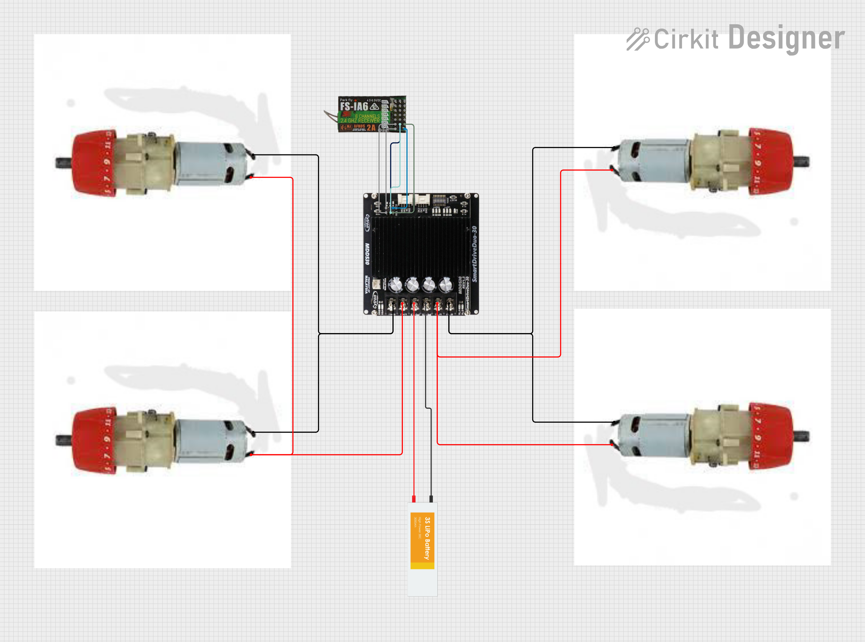 Open Project in Cirkit Designer
Explore Projects Built with FlySky_10_Channel
Open Project in Cirkit DesignerOpen Project in Cirkit DesignerOpen Project in Cirkit DesignerOpen Project in Cirkit DesignerTechnical Specifications
Below are the key technical details of the FlySky_10_Channel (FS-iA10B):
General Specifications
- Frequency Range: 2.405 – 2.475 GHz
- Modulation Type: GFSK (Gaussian Frequency Shift Keying)
- Number of Channels: 10
- Operating Voltage: 4.0 – 6.5 V
- Operating Current: ≤ 100 mA
- Antenna Type: Dual antennas for enhanced signal stability
- Range: Up to 500 meters (line of sight)
- Compatibility: FlySky transmitters using the AFHDS 2A protocol
Pin Configuration and Descriptions
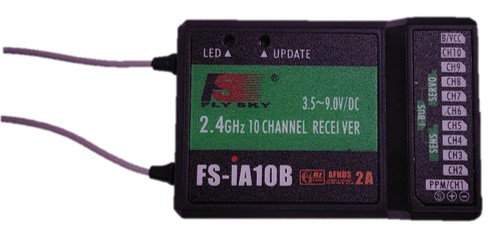
The FS-iA10B receiver features multiple pins for connecting servos, ESCs, and other peripherals. Below is the pin configuration:
| Pin Number | Label | Description |
|---|---|---|
| 1 | CH1 | Channel 1 output for servo or ESC |
| 2 | CH2 | Channel 2 output for servo or ESC |
| 3 | CH3 | Channel 3 output for servo or ESC |
| 4 | CH4 | Channel 4 output for servo or ESC |
| 5 | CH5 | Channel 5 output for servo or accessory |
| 6 | CH6 | Channel 6 output for servo or accessory |
| 7 | CH7 | Channel 7 output for servo or accessory |
| 8 | CH8 | Channel 8 output for servo or accessory |
| 9 | CH9 | Channel 9 output for servo or accessory |
| 10 | CH10 | Channel 10 output for servo or accessory |
| 11 | BIND/VCC | Binding port and power input (4.0 – 6.5 V) |
| 12 | i-BUS/S.BUS | i-BUS or S.BUS output for digital communication with compatible devices |
| 13 | PPM | PPM signal output for connecting to flight controllers or other PPM-compatible |
| 14 | GND | Ground connection |
Usage Instructions
How to Use the FS-iA10B in a Circuit
- Powering the Receiver: Connect a power source (4.0 – 6.5 V) to the BIND/VCC pin and GND pin. Ensure the power supply is stable to avoid signal interruptions.
- Binding the Receiver:
- Turn on the transmitter and set it to binding mode.
- Connect the binding plug to the BIND/VCC port on the receiver.
- Power on the receiver. The LED will flash, indicating it is in binding mode.
- Once the binding process is complete, the LED will remain solid.
- Remove the binding plug and restart the receiver.
- Connecting Peripherals:
- Connect servos, ESCs, or other devices to the appropriate channel pins (CH1–CH10).
- For digital communication, use the i-BUS/S.BUS or PPM pin to connect to a flight controller or compatible device.
- Testing:
- Verify that all connected devices respond correctly to transmitter inputs.
- Perform a range test to ensure reliable communication.
Important Considerations and Best Practices
- Antenna Placement: Ensure the receiver's dual antennas are positioned at 90-degree angles to maximize signal reception.
- Power Supply: Use a regulated power source within the specified voltage range to prevent damage to the receiver.
- Interference: Avoid operating the system near strong electromagnetic sources to minimize interference.
- Failsafe Settings: Configure failsafe settings on the transmitter to ensure safe operation in case of signal loss.
Example Code for Arduino UNO
The FS-iA10B can be connected to an Arduino UNO using the PPM output. Below is an example code snippet to read PPM signals:
#include <PPMReader.h>

// Define the PPM input pin and number of channels
#define PPM_PIN 2
#define NUM_CHANNELS 10

// Create a PPMReader object
PPMReader ppm(PPM_PIN, NUM_CHANNELS);

void setup() {
  Serial.begin(9600); // Initialize serial communication
  Serial.println("FS-iA10B PPM Reader Initialized");
}

void loop() {
  // Loop through all channels and print their values
  for (int channel = 1; channel <= NUM_CHANNELS; channel++) {
    int value = ppm.latestValidChannelValue(channel, 0);
    Serial.print("Channel ");
    Serial.print(channel);
    Serial.print(": ");
    Serial.println(value);
  }
  delay(100); // Delay to avoid flooding the serial monitor
}
Note: Connect the PPM pin of the FS-iA10B to pin 2 of the Arduino UNO. Ensure the receiver is powered correctly.
Troubleshooting and FAQs
Common Issues and Solutions
Receiver Not Binding:
- Ensure the transmitter is in binding mode.
- Verify the binding plug is correctly connected to the BIND/VCC port.
- Check the power supply to the receiver.
Signal Loss or Interference:
- Reposition the receiver antennas for better signal reception.
- Avoid operating near devices that emit strong electromagnetic interference.
Servos Not Responding:
- Verify the servo connections to the correct channel pins.
- Check the transmitter settings to ensure the channels are configured correctly.
PPM Signal Not Detected by Arduino:
- Ensure the PPM pin is connected to the correct Arduino pin.
- Verify the Arduino code and library setup.
FAQs
Can the FS-iA10B be used with other brands of transmitters? No, the FS-iA10B is compatible only with FlySky transmitters using the AFHDS 2A protocol.
What is the maximum range of the FS-iA10B? The receiver has a maximum range of up to 500 meters in line-of-sight conditions.
Can I use fewer than 10 channels? Yes, you can use as many channels as required for your application.
Is the FS-iA10B waterproof? No, the receiver is not waterproof. Protect it from moisture during use.
This documentation provides a comprehensive guide to using the FlySky_10_Channel (FS-iA10B) receiver effectively. For further assistance, refer to the manufacturer's user manual or contact technical support.