How to Use QTRX-HD-07RC Reflectance Sensor Array: Examples, Pinouts, and Specs
Introduction
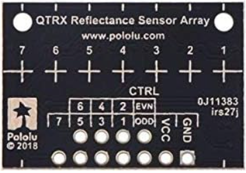
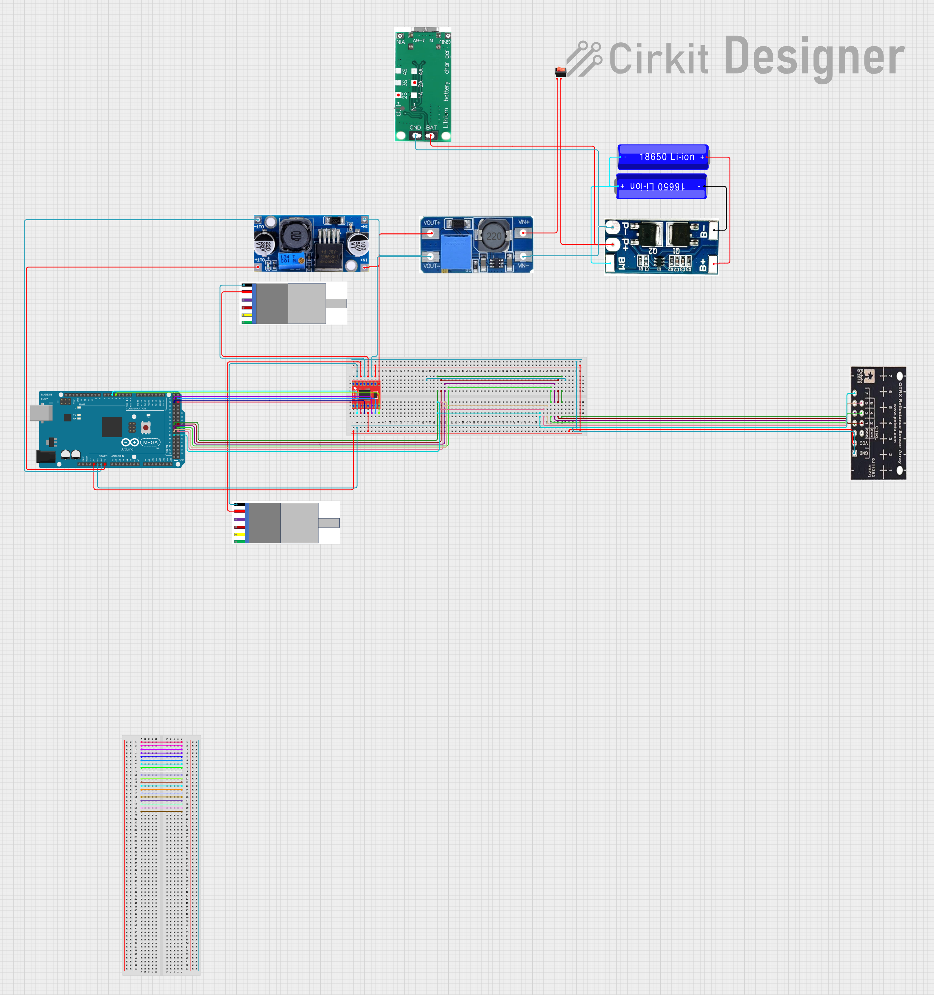
The QTRX-HD-07RC Reflectance Sensor Array is an advanced electronic component designed by Pololu for detecting variations in reflectivity on surfaces. This sensor array is equipped with seven individual sensors, making it an ideal choice for precision applications such as line-following robots, edge detection, and surface monitoring. Its high-resolution sensing capability allows for accurate and reliable readings, which are crucial in robotics and automation projects.
Explore Projects Built with QTRX-HD-07RC Reflectance Sensor Array
Explore Projects Built with QTRX-HD-07RC Reflectance Sensor Array
Common Applications and Use Cases
- Line-following robots for competitions or educational purposes
- Edge detection to prevent robots from falling off tables
- Surface characterization for material sorting systems
- Position control in conveyor systems
Technical Specifications
Key Technical Details
- Operating Voltage: 3.3V to 5V
- Average Current Consumption: 100 mA
- Output Format: Analog voltage
- Optimal Sensing Distance: 0.5 cm to 1 cm
- Maximum Recommended Sensing Distance: 3 cm
- Dimensions: 2.95" x 0.5" x 0.125" (without header pins)
Pin Configuration and Descriptions
| Pin Number | Name | Description |
|---|---|---|
| 1 | VCC | Power supply (3.3V to 5V) |
| 2 | GND | Ground connection |
| 3 | OUT1 | Analog voltage output for sensor 1 |
| 4 | OUT2 | Analog voltage output for sensor 2 |
| 5 | OUT3 | Analog voltage output for sensor 3 |
| 6 | OUT4 | Analog voltage output for sensor 4 |
| 7 | OUT5 | Analog voltage output for sensor 5 |
| 8 | OUT6 | Analog voltage output for sensor 6 |
| 9 | OUT7 | Analog voltage output for sensor 7 |
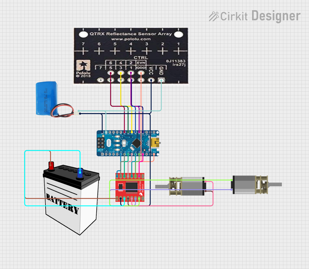
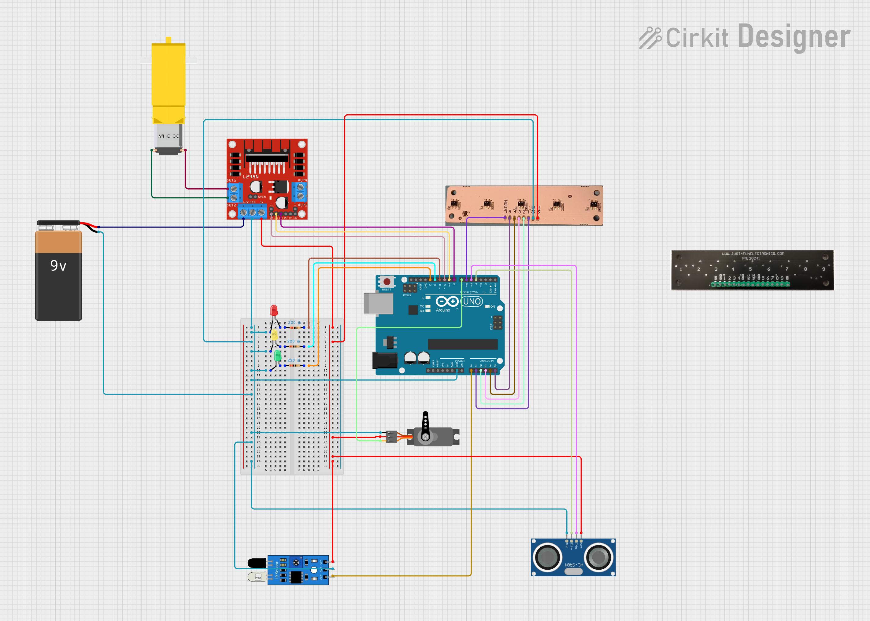
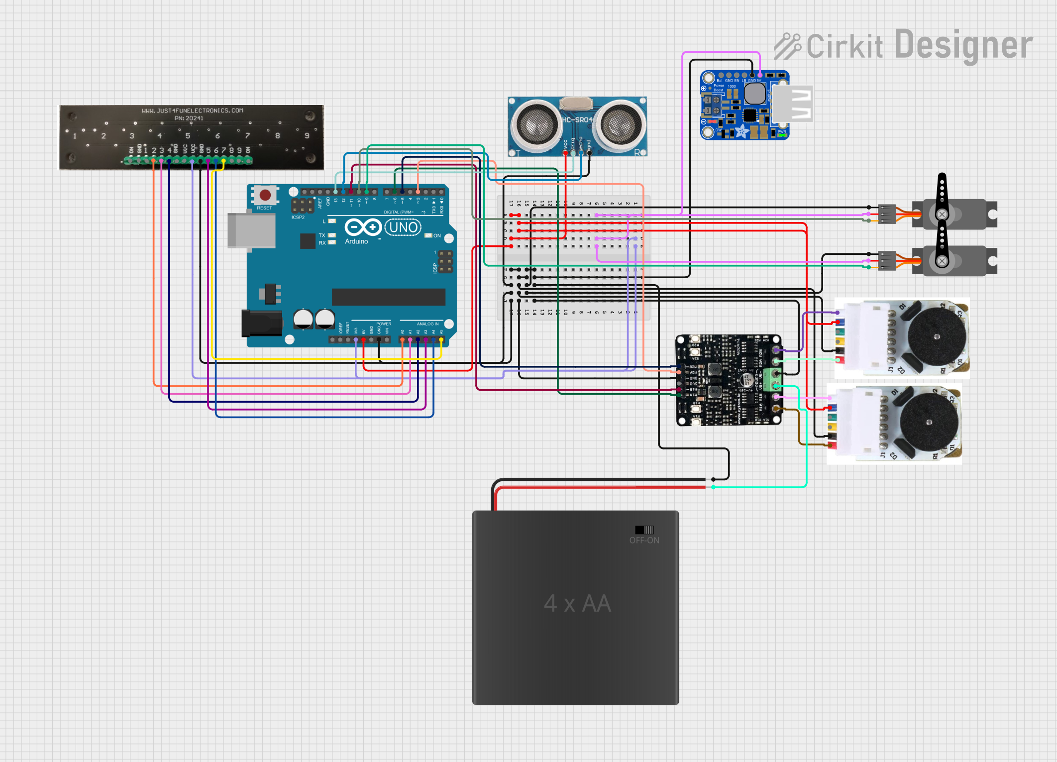
Usage Instructions
How to Use the Component in a Circuit
- Power Supply: Connect the VCC pin to a 3.3V or 5V power supply and the GND pin to the ground.
- Sensor Outputs: Connect each OUT pin to an analog input on your microcontroller, such as an Arduino UNO.
- Calibration: Before using the sensor array, calibrate it to the specific surface and lighting conditions of your application.
Important Considerations and Best Practices
- Ensure that the sensors are at the optimal sensing distance from the surface for accurate readings.
- Avoid exposing the sensor to direct sunlight or other strong light sources that could interfere with its operation.
- Use a clean, uniform surface for line-following applications to maintain consistent sensor readings.
- Implement a filtering algorithm in your code to smooth out noise in the sensor readings.
Example Code for Arduino UNO
#include <QTRSensors.h>

// Define the number of sensors and the analog pins they are connected to
#define NUM_SENSORS   7
#define TIMEOUT       2500
#define EMITTER_PIN   QTR_NO_EMITTER_PIN

// Create an object for the sensor array
QTRSensorsAnalog qtra((unsigned char[]) {A0, A1, A2, A3, A4, A5, A6},
                      NUM_SENSORS, TIMEOUT, EMITTER_PIN);

unsigned int sensorValues[NUM_SENSORS];

void setup() {
  // Initialize serial communication
  Serial.begin(9600);

  // Calibrate the sensors
  for (int i = 0; i < 400; i++) {
    qtra.calibrate();
  }
}

void loop() {
  // Read calibrated sensor values and obtain a measure from 0 to 2500,
  // where 0 indicates maximum reflectance and 2500 indicates minimum reflectance
  qtra.read(sensorValues);

  // Print the sensor values as comma-separated values
  for (int i = 0; i < NUM_SENSORS; i++) {
    Serial.print(sensorValues[i]);
    Serial.print(i < NUM_SENSORS - 1 ? ',' : '\n');
  }

  delay(250); // Wait for 250 milliseconds before reading the sensors again
}
Troubleshooting and FAQs
Common Issues Users Might Face
- Inconsistent Readings: Ensure that the sensor array is mounted at a consistent height from the surface. Clean the surface and the sensors to remove any dust or debris.
- No Readings: Check the power supply and wiring connections. Ensure that the sensor pins are connected to the correct analog inputs on the microcontroller.
- Erratic Behavior: Implement software debouncing or filtering to smooth out the sensor readings.
Solutions and Tips for Troubleshooting
- Calibration: Regularly calibrate the sensor array for the specific surface and lighting conditions.
- Wiring: Use short and secure connections to minimize electrical noise and interference.
- Code Debugging: Add serial print statements in your code to monitor sensor values and behavior during operation.
FAQs
Q: Can the sensor array detect colors? A: The QTRX-HD-07RC is designed to detect reflectivity levels, not colors. It can distinguish between light and dark surfaces.
Q: What is the maximum operating voltage for the sensor array? A: The maximum operating voltage is 5V. Exceeding this voltage may damage the sensors.
Q: How do I clean the sensor surfaces? A: Use a soft, dry cloth to gently wipe the sensor surfaces. Avoid using liquids or abrasive materials.
Q: Can I use this sensor array outdoors? A: The sensor array can be used outdoors, but it should be shielded from direct sunlight and extreme weather conditions for accurate performance.