
How to Use IDG300: Examples, Pinouts, and Specs
 Design with IDG300 in Cirkit Designer
Introduction
The IDG300 is a dual-axis angular rate sensor designed to measure rotational motion with high precision and low noise. This gyroscope is ideal for applications requiring accurate motion sensing, such as robotics, aerospace systems, gaming devices, and motion tracking. Its compact design and reliable performance make it a popular choice for both industrial and consumer electronics.
Explore Projects Built with IDG300
 Open Project in Cirkit Designer
 Open Project in Cirkit Designer
 Open Project in Cirkit Designer
 Open Project in Cirkit Designer
Explore Projects Built with IDG300
Open Project in Cirkit DesignerOpen Project in Cirkit DesignerOpen Project in Cirkit DesignerOpen Project in Cirkit DesignerTechnical Specifications
The following table outlines the key technical details of the IDG300:
| Parameter | Value |
|---|---|
| Measurement Axes | Dual-axis (X and Y) |
| Measurement Range | ±500°/s |
| Sensitivity | 2.0 mV/°/s |
| Supply Voltage | 2.7V to 3.6V |
| Operating Temperature | -40°C to +85°C |
| Noise Density | 0.02°/s/√Hz |
| Output Type | Analog |
| Package Type | LGA-16 (4mm x 4mm) |
Pin Configuration and Descriptions
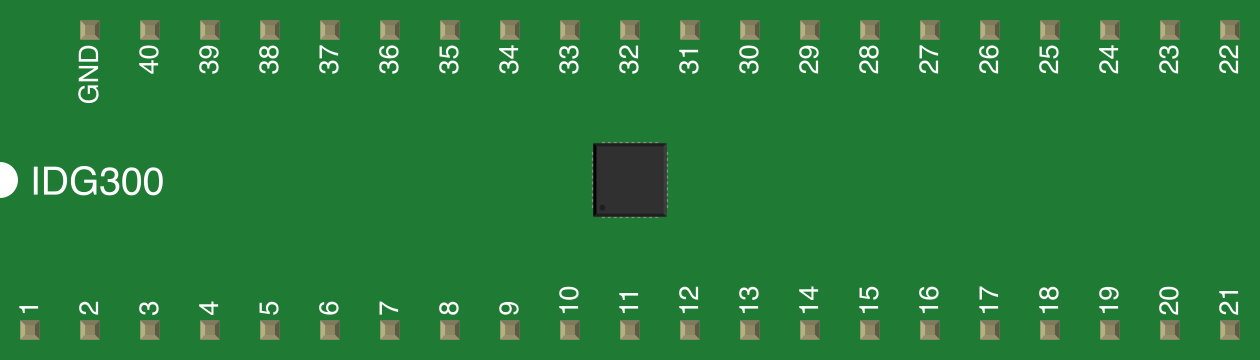
The IDG300 has 16 pins, with the following configuration:
| Pin Number | Pin Name | Description |
|---|---|---|
| 1 | VDD | Power supply (2.7V to 3.6V) |
| 2 | GND | Ground |
| 3 | XOUT | X-axis angular rate output |
| 4 | YOUT | Y-axis angular rate output |
| 5 | ST1 | Self-test input for X-axis |
| 6 | ST2 | Self-test input for Y-axis |
| 7 | NC | Not connected |
| 8 | NC | Not connected |
| 9 | NC | Not connected |
| 10 | NC | Not connected |
| 11 | VREF | Reference voltage output |
| 12 | C1P | External capacitor connection (positive terminal) |
| 13 | C1N | External capacitor connection (negative terminal) |
| 14 | C2P | External capacitor connection (positive terminal) |
| 15 | C2N | External capacitor connection (negative terminal) |
| 16 | NC | Not connected |
Note: Pins labeled "NC" should remain unconnected during circuit design.
Usage Instructions
How to Use the IDG300 in a Circuit
- Power Supply: Connect the VDD pin to a stable power source within the range of 2.7V to 3.6V. Connect the GND pin to the ground of the circuit.
- Output Connections: Connect the XOUT and YOUT pins to an analog-to-digital converter (ADC) or microcontroller to read the angular rate data.
- Reference Voltage: Use the VREF pin as a reference voltage for the ADC if required.
- External Capacitors: Connect appropriate capacitors to the C1P, C1N, C2P, and C2N pins as specified in the datasheet to ensure proper operation.
- Self-Test: To verify the functionality of the sensor, apply a logic high signal to the ST1 or ST2 pins to activate the self-test mode for the respective axis.
Important Considerations and Best Practices
- Decoupling Capacitors: Place a 0.1 µF ceramic capacitor close to the VDD pin to reduce power supply noise.
- Mounting Orientation: Ensure the sensor is mounted correctly to align with the desired measurement axes.
- Signal Filtering: Use low-pass filters on the XOUT and YOUT signals to reduce high-frequency noise.
- Temperature Compensation: Account for temperature variations in your application, as they may slightly affect sensor performance.
Example: Connecting IDG300 to Arduino UNO
Below is an example of how to interface the IDG300 with an Arduino UNO to read angular rate data:
// Define analog input pins for X and Y outputs
const int xPin = A0; // XOUT connected to A0
const int yPin = A1; // YOUT connected to A1

void setup() {
  Serial.begin(9600); // Initialize serial communication at 9600 baud
}

void loop() {
  // Read analog values from the IDG300
  int xValue = analogRead(xPin); // Read X-axis angular rate
  int yValue = analogRead(yPin); // Read Y-axis angular rate

  // Convert analog values to voltage (assuming 5V reference)
  float xVoltage = xValue * (5.0 / 1023.0);
  float yVoltage = yValue * (5.0 / 1023.0);

  // Print the results to the Serial Monitor
  Serial.print("X Voltage: ");
  Serial.print(xVoltage);
  Serial.print(" V, Y Voltage: ");
  Serial.print(yVoltage);
  Serial.println(" V");

  delay(500); // Wait for 500ms before the next reading
}
Note: Ensure the Arduino's ADC reference voltage matches the IDG300's output voltage range for accurate readings.
Troubleshooting and FAQs
Common Issues and Solutions
No Output Signal:
- Verify that the VDD and GND pins are properly connected.
- Check for loose connections or damaged wires.
- Ensure the external capacitors are correctly installed.
High Noise in Output:
- Add low-pass filters to the XOUT and YOUT signals.
- Ensure the power supply is stable and free from noise.
Incorrect Readings:
- Confirm the sensor is mounted in the correct orientation.
- Calibrate the sensor to account for any offsets or drift.
Self-Test Not Working:
- Ensure the ST1 or ST2 pins are receiving a proper logic high signal.
- Check the datasheet for the required self-test conditions.
FAQs
Q: Can the IDG300 measure angular velocity beyond ±500°/s?
A: No, the IDG300 is designed for a maximum range of ±500°/s. Exceeding this range may result in inaccurate readings or damage to the sensor.
Q: Is the IDG300 compatible with 5V systems?
A: The IDG300 operates at 2.7V to 3.6V. Use a level shifter or voltage divider if interfacing with a 5V system.
Q: How do I calibrate the IDG300?
A: Calibration involves measuring the sensor's output at rest to determine the zero-rate offset. Subtract this offset from subsequent readings to improve accuracy.
Q: Can I use the IDG300 for 3D motion tracking?
A: The IDG300 measures angular velocity on two axes (X and Y). For 3D motion tracking, you would need an additional sensor to measure the Z-axis.