
How to Use MC34063: Examples, Pinouts, and Specs
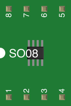
 Design with MC34063 in Cirkit Designer
Introduction
The MC34063 is a versatile DC-DC converter integrated circuit (IC) designed for step-up (boost), step-down (buck), or voltage inverter applications. It features an internal switch, making it an excellent choice for low-cost and efficient power supply designs. With an input voltage range of 3V to 40V, the MC34063 is suitable for a wide variety of applications, including battery-powered devices, automotive electronics, and general-purpose power supplies.
Explore Projects Built with MC34063
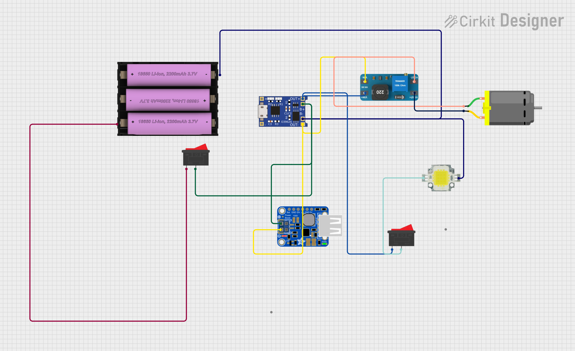 Open Project in Cirkit Designer
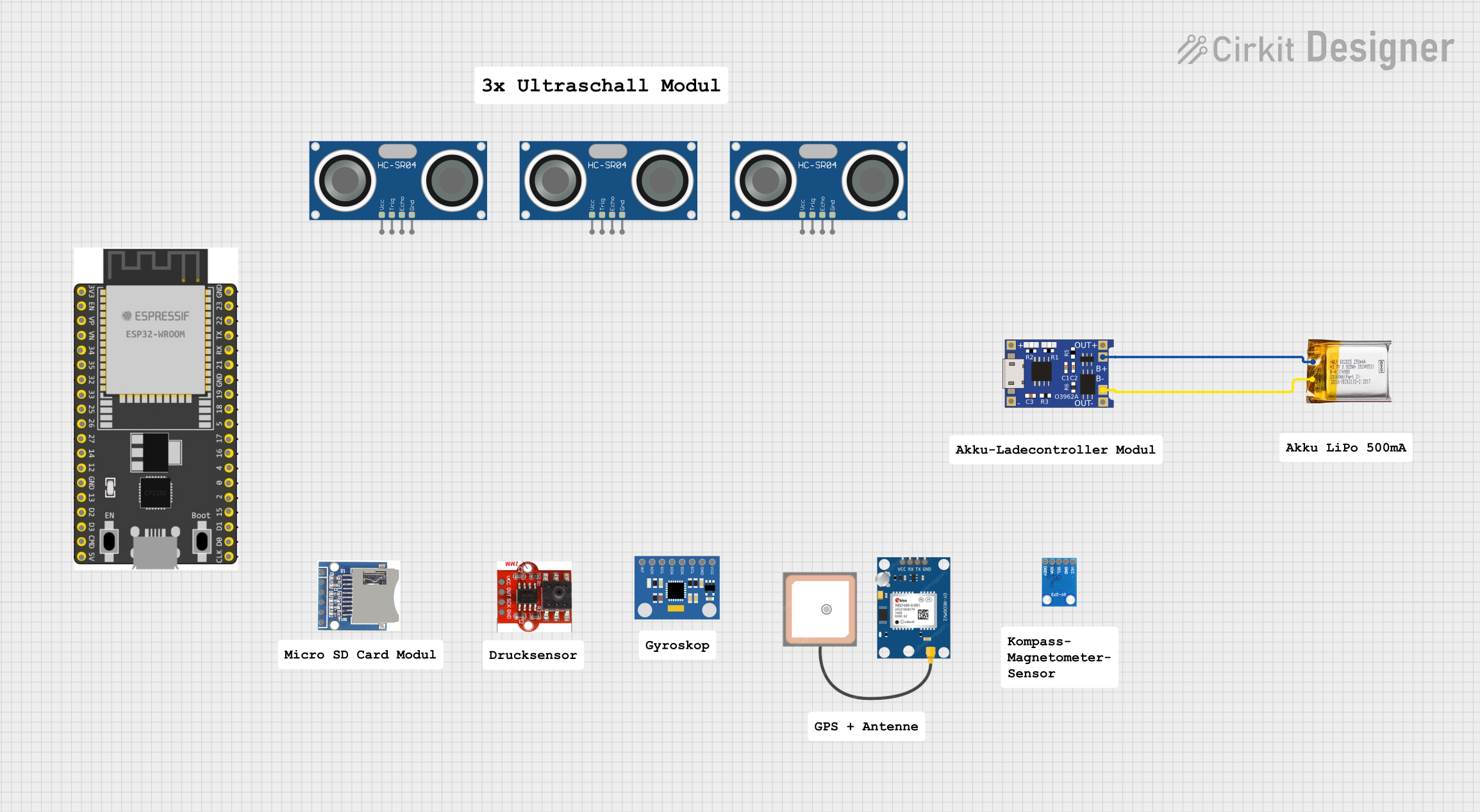 Open Project in Cirkit Designer
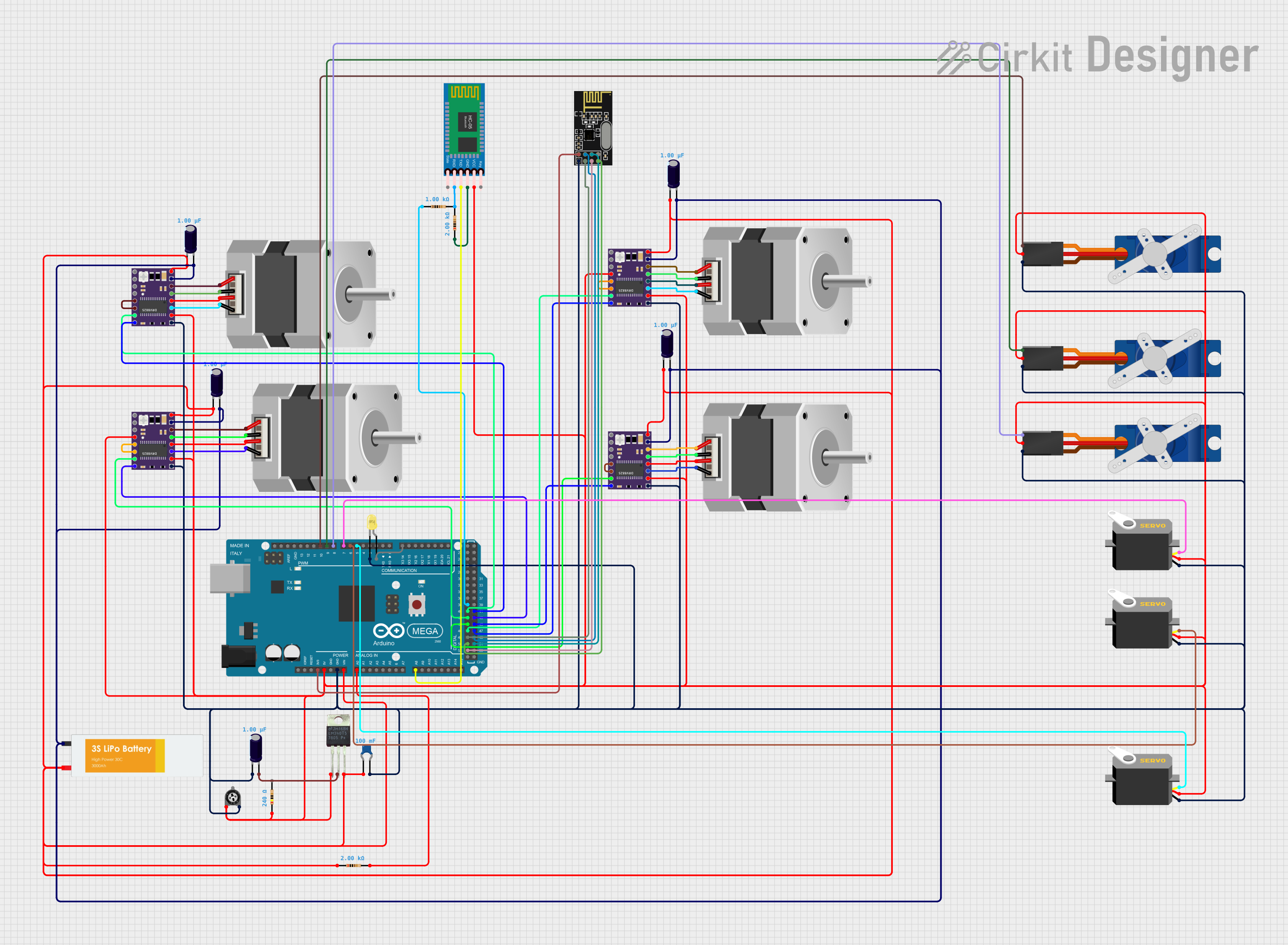 Open Project in Cirkit Designer
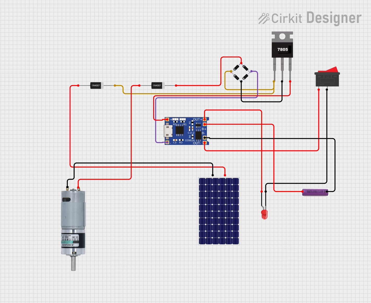 Open Project in Cirkit Designer
Explore Projects Built with MC34063
Open Project in Cirkit DesignerOpen Project in Cirkit DesignerOpen Project in Cirkit DesignerOpen Project in Cirkit DesignerCommon Applications
- Step-up (boost) converters for increasing voltage
- Step-down (buck) converters for reducing voltage
- Voltage inverters for generating negative voltages
- Battery chargers
- LED drivers
- Low-cost power supply designs
Technical Specifications
The MC34063 is a highly flexible IC with the following key technical specifications:
| Parameter | Value |
|---|---|
| Input Voltage Range | 3V to 40V |
| Output Voltage Range | Adjustable (depends on external components) |
| Output Current | Up to 1.5A (with external components) |
| Switching Frequency | Adjustable, up to 100 kHz |
| Efficiency | Up to 90% (depending on design) |
| Internal Switch Voltage | Up to 40V |
| Internal Switch Current | 1.5A |
| Operating Temperature Range | -40°C to +85°C |
Pin Configuration and Descriptions
The MC34063 is typically available in an 8-pin DIP or SOIC package. Below is the pin configuration:
| Pin Number | Pin Name | Description |
|---|---|---|
| 1 | Switch Collector (SWC) | Collector of the internal NPN power switch. Connect to the inductor. |
| 2 | Switch Emitter (SWE) | Emitter of the internal NPN power switch. Connect to ground or current sense. |
| 3 | Timing Capacitor (CT) | Sets the oscillator frequency. Connect a capacitor to ground. |
| 4 | Ground (GND) | Ground reference for the IC. |
| 5 | Comparator Inverting Input (IN-) | Feedback input for voltage regulation. Connect to a voltage divider. |
| 6 | VCC | Power supply input (3V to 40V). |
| 7 | Ipk Sense | Current sense input for limiting peak current. |
| 8 | Driver Collector (DRC) | Drives the base of an external transistor (optional). |
Usage Instructions
The MC34063 can be configured for step-up, step-down, or inverter applications by selecting appropriate external components such as resistors, capacitors, and inductors. Below are general guidelines for using the IC:
Step-by-Step Instructions
- Determine the Application Type: Decide whether you need a step-up, step-down, or inverter circuit.
- Calculate External Components: Use the formulas provided in the MC34063 datasheet to calculate the values of the inductor, timing capacitor, and resistors for your desired output voltage and current.
- Connect the Circuit:
- Connect the input voltage to the VCC pin (Pin 6).
- Use a voltage divider to provide feedback to the IN- pin (Pin 5).
- Connect the inductor to the SWC pin (Pin 1) and the SWE pin (Pin 2) to ground.
- Add a timing capacitor to the CT pin (Pin 3) to set the switching frequency.
- Use a diode and output capacitor to filter the output voltage.
- Test the Circuit: Verify the output voltage and current using a multimeter or oscilloscope.
Important Considerations
- Inductor Selection: Choose an inductor with a current rating higher than the peak current of your circuit.
- Diode Selection: Use a fast-recovery or Schottky diode to minimize losses.
- Thermal Management: Ensure proper heat dissipation, especially for high-current applications.
- Oscillator Frequency: Adjust the timing capacitor to set the desired switching frequency. Higher frequencies reduce the size of external components but may decrease efficiency.
Example: Step-Down Converter with Arduino UNO
Below is an example of using the MC34063 as a step-down converter to power an Arduino UNO from a 12V input:
Circuit Design
- Input Voltage: 12V
- Output Voltage: 5V
- Output Current: 500mA
Arduino Code
// Example code to monitor the output voltage of the MC34063 circuit
// using an Arduino UNO. Connect the output voltage to an analog pin.

const int voltagePin = A0; // Analog pin connected to the MC34063 output
const float referenceVoltage = 5.0; // Arduino reference voltage (5V)
const float voltageDividerRatio = 2.0; // Adjust based on your resistor divider

void setup() {
  Serial.begin(9600); // Initialize serial communication
}

void loop() {
  int analogValue = analogRead(voltagePin); // Read the analog pin
  float outputVoltage = (analogValue / 1023.0) * referenceVoltage * voltageDividerRatio;

  // Print the output voltage to the Serial Monitor
  Serial.print("Output Voltage: ");
  Serial.print(outputVoltage);
  Serial.println(" V");

  delay(1000); // Wait for 1 second before the next reading
}
Troubleshooting and FAQs
Common Issues
Output Voltage is Incorrect:
- Check the feedback resistor values and ensure they match the calculated values.
- Verify the input voltage is within the specified range (3V to 40V).
- Ensure the inductor and diode are correctly rated for the application.
Circuit Overheats:
- Ensure the inductor and diode have adequate current ratings.
- Check for proper heat dissipation and consider adding a heatsink if necessary.
Oscillator Frequency is Unstable:
- Verify the timing capacitor value and ensure it is connected properly.
- Check for noise or interference in the circuit.
No Output Voltage:
- Ensure all connections are correct and components are soldered properly.
- Verify the IC is not damaged and the input voltage is present.
FAQs
Q: Can the MC34063 handle high output currents?
A: The MC34063 can handle up to 1.5A with proper external components, but for higher currents, consider using an external transistor.
Q: How do I improve efficiency?
A: Use a Schottky diode, minimize switching losses by optimizing the frequency, and select high-quality inductors and capacitors.
Q: Can I use the MC34063 for negative voltage generation?
A: Yes, the MC34063 can be configured as a voltage inverter to generate negative voltages.
Q: What is the maximum switching frequency?
A: The MC34063 can operate at switching frequencies up to 100 kHz, depending on the timing capacitor value.
By following this documentation, you can effectively design and troubleshoot circuits using the MC34063 DC-DC converter IC.