How to Use 5a de doble vía ESC 2s-3s placa: Examples, Pinouts, and Specs
Introduction
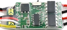
The 5A dual-channel Electronic Speed Controller (ESC) is a compact and efficient device designed to control the speed of brushless motors in remote-controlled (RC) vehicles. It supports 2S to 3S lithium polymer (LiPo) batteries, making it ideal for small-scale RC cars, boats, and drones. This ESC is capable of handling up to 5A of continuous current per channel, providing precise motor control for smooth operation.
Explore Projects Built with 5a de doble vía ESC 2s-3s placa


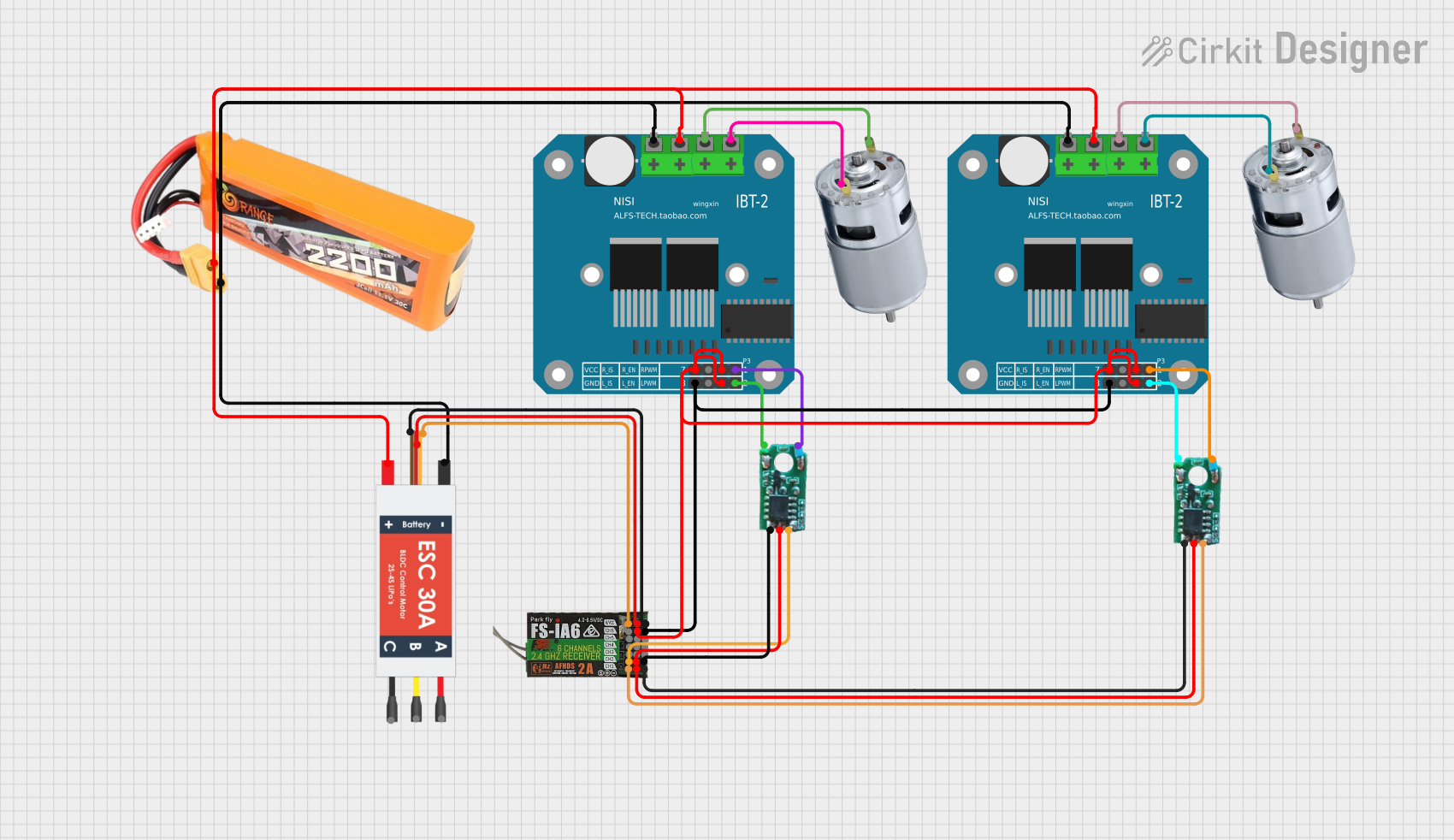

Explore Projects Built with 5a de doble vía ESC 2s-3s placa
Common Applications and Use Cases
- RC cars, boats, and drones
- Robotics projects requiring dual motor control
- DIY projects involving brushless motor speed regulation
- Educational kits for learning motor control and electronics
Technical Specifications
Below are the key technical details of the 5A dual-channel ESC:
| Parameter | Specification |
|---|---|
| Input Voltage | 7.4V to 11.1V (2S to 3S LiPo) |
| Continuous Current | 5A per channel |
| Peak Current | 8A per channel (short duration) |
| Motor Type Supported | Brushless motors |
| Control Signal Input | PWM (Pulse Width Modulation) |
| Operating Frequency | 20 kHz |
| Dimensions | 30mm x 20mm x 8mm |
| Weight | 10g |
Pin Configuration and Descriptions
The ESC has the following pin configuration:
| Pin Name | Description |
|---|---|
| VIN | Positive input voltage from the 2S-3S LiPo battery (7.4V to 11.1V). |
| GND | Ground connection for the power supply and control signals. |
| M1+ | Positive terminal for Motor 1. |
| M1- | Negative terminal for Motor 1. |
| M2+ | Positive terminal for Motor 2. |
| M2- | Negative terminal for Motor 2. |
| PWM1 | PWM input signal for controlling the speed of Motor 1. |
| PWM2 | PWM input signal for controlling the speed of Motor 2. |
Usage Instructions
How to Use the Component in a Circuit
- Power Connection: Connect the VIN and GND pins to a 2S or 3S LiPo battery. Ensure the battery voltage is within the specified range (7.4V to 11.1V).
- Motor Connection: Connect the brushless motors to the M1+/M1- and M2+/M2- terminals. Ensure the motors are compatible with the ESC's specifications.
- Control Signal: Use a microcontroller (e.g., Arduino UNO) to generate PWM signals for the PWM1 and PWM2 pins. These signals control the speed of Motor 1 and Motor 2, respectively.
- Testing: Gradually increase the PWM duty cycle to test motor speed. Ensure the motors spin smoothly without overheating.
Important Considerations and Best Practices
- Battery Selection: Use only 2S or 3S LiPo batteries. Exceeding the voltage range may damage the ESC.
- Heat Management: Ensure proper ventilation to prevent the ESC from overheating during operation.
- PWM Signal Range: Use a PWM signal with a frequency of 20 kHz and a duty cycle range of 0% to 100%.
- Reverse Polarity Protection: Double-check connections to avoid reversing the polarity of the power supply, which can damage the ESC.
Example Code for Arduino UNO
Below is an example Arduino code to control the 5A dual-channel ESC using PWM signals:
// Example code to control a 5A dual-channel ESC with Arduino UNO
// Connect PWM1 to pin 9 and PWM2 to pin 10 on the Arduino

const int pwmPin1 = 9;  // PWM signal for Motor 1
const int pwmPin2 = 10; // PWM signal for Motor 2

void setup() {
  pinMode(pwmPin1, OUTPUT); // Set pin 9 as output
  pinMode(pwmPin2, OUTPUT); // Set pin 10 as output
}

void loop() {
  // Gradually increase speed of Motor 1
  for (int speed = 0; speed <= 255; speed++) {
    analogWrite(pwmPin1, speed); // Write PWM signal to Motor 1
    delay(20); // Small delay for smooth acceleration
  }

  // Gradually decrease speed of Motor 1
  for (int speed = 255; speed >= 0; speed--) {
    analogWrite(pwmPin1, speed); // Write PWM signal to Motor 1
    delay(20); // Small delay for smooth deceleration
  }

  // Gradually increase speed of Motor 2
  for (int speed = 0; speed <= 255; speed++) {
    analogWrite(pwmPin2, speed); // Write PWM signal to Motor 2
    delay(20); // Small delay for smooth acceleration
  }

  // Gradually decrease speed of Motor 2
  for (int speed = 255; speed >= 0; speed--) {
    analogWrite(pwmPin2, speed); // Write PWM signal to Motor 2
    delay(20); // Small delay for smooth deceleration
  }
}
Troubleshooting and FAQs
Common Issues and Solutions
Motors Not Spinning:
- Cause: Incorrect wiring or no PWM signal.
- Solution: Verify motor connections and ensure the PWM signals are being sent correctly.
Overheating ESC:
- Cause: Prolonged operation at high current or insufficient ventilation.
- Solution: Reduce motor load or improve airflow around the ESC.
Erratic Motor Behavior:
- Cause: Noise in the PWM signal or incompatible motor.
- Solution: Use shielded cables for PWM signals and ensure the motor is compatible with the ESC.
No Power to ESC:
- Cause: Incorrect battery connection or low battery voltage.
- Solution: Check the battery polarity and ensure the voltage is within the specified range.
FAQs
Q1: Can I use this ESC with a 4S LiPo battery?
A1: No, this ESC is designed for 2S to 3S LiPo batteries only. Using a 4S battery may damage the ESC.
Q2: Can I control both motors independently?
A2: Yes, the ESC has separate PWM inputs (PWM1 and PWM2) for independent control of each motor.
Q3: What happens if I reverse the motor connections?
A3: Reversing the motor connections will change the direction of motor rotation. This is not harmful to the ESC or motor.
Q4: Is this ESC compatible with brushed motors?
A4: No, this ESC is specifically designed for brushless motors. It is not compatible with brushed motors.