How to Use LED Matrix 64x32: Examples, Pinouts, and Specs
Introduction
The Adafruit 64x32 LED Matrix is a large panel that contains a grid of 2048 LEDs arranged in 64 columns and 32 rows. These panels are commonly used to create vibrant and dynamic displays for advertising, public information, and interactive installations. They are capable of displaying a wide range of colors by combining red, green, and blue LEDs (RGB) at each pixel point.
Explore Projects Built with LED Matrix 64x32


Explore Projects Built with LED Matrix 64x32
Common Applications and Use Cases
- Digital signage and billboards
- Scoreboards for sports events
- Interactive art installations
- Custom gaming displays
- Real-time data visualization
Technical Specifications
Key Technical Details
- Resolution: 64x32 pixels
- Color: RGB, capable of 16 million colors
- Voltage: 5V DC
- Current: 2A-4A (depending on brightness and color)
- Power Consumption: ~20W-40W
- Refresh Rate: ≥120Hz
- Viewing Angle: >160 degrees
- Lifespan: ≥50,000 hours
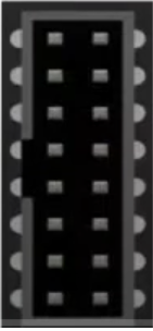
Pin Configuration and Descriptions
| Pin Number | Name | Description |
|---|---|---|
| 1 | GND | Ground |
| 2 | VCC | Power supply (5V DC) |
| 3 | CLK | Clock signal |
| 4 | LAT | Latch signal |
| 5 | OE | Output enable |
| 6 | A | Address line A |
| 7 | B | Address line B |
| 8 | C | Address line C |
| 9 | D | Address line D (for 1/16 scan rate) |
| 10 | R1 | Red data (top half) |
| 11 | G1 | Green data (top half) |
| 12 | B1 | Blue data (top half) |
| 13 | R2 | Red data (bottom half) |
| 14 | G2 | Green data (bottom half) |
| 15 | B2 | Blue data (bottom half) |
Usage Instructions
How to Use the Component in a Circuit
- Power Supply: Ensure that you have a stable 5V power supply that can deliver sufficient current (2A-4A).
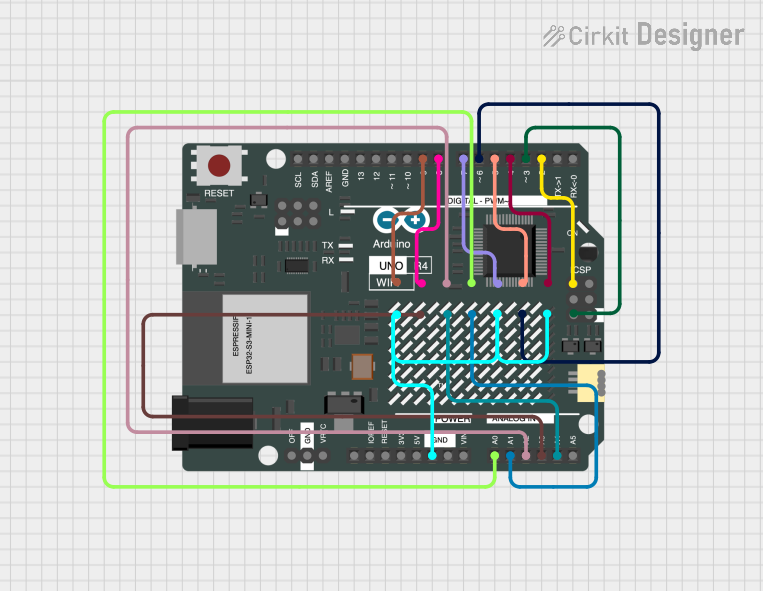
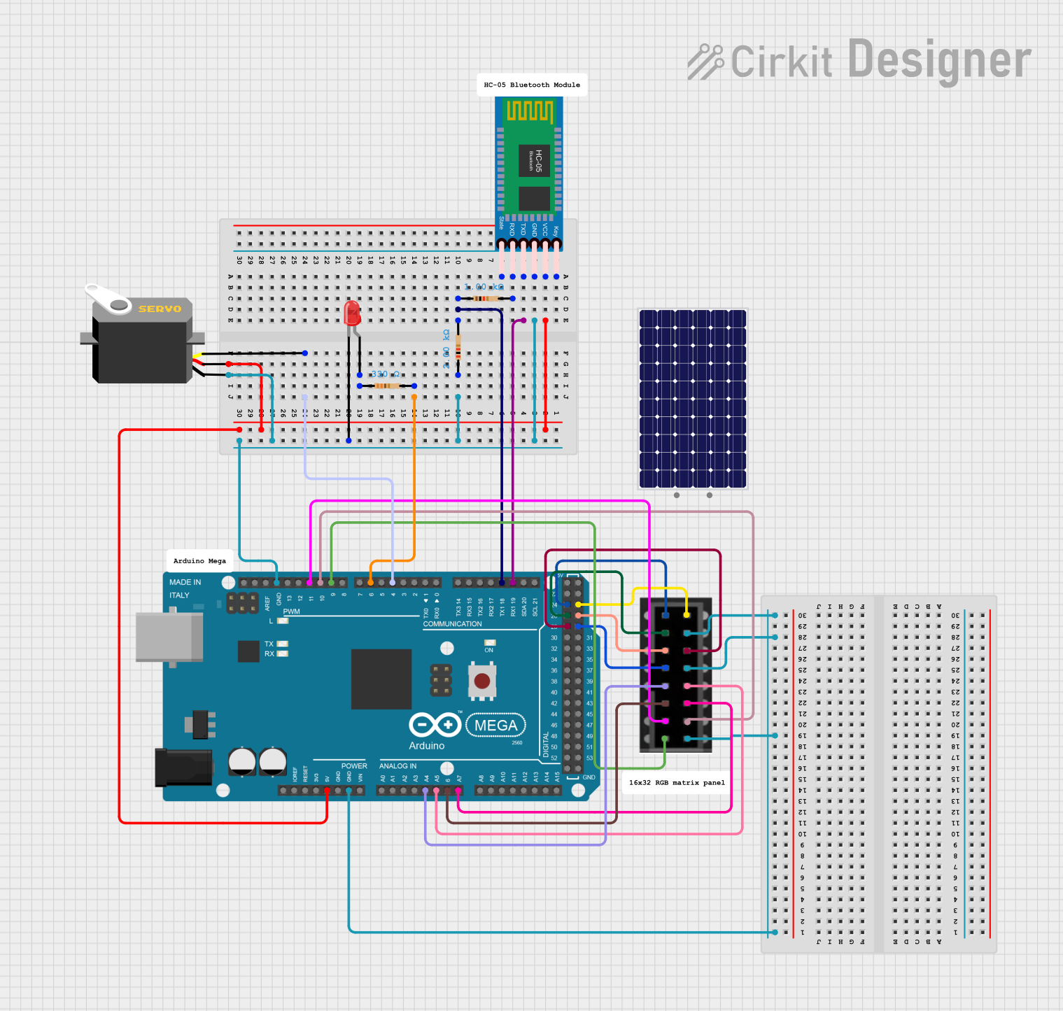
- Connecting to a Microcontroller: Use a microcontroller like an Arduino UNO to control the LED matrix. You will need to connect the pins from the matrix to the corresponding pins on the Arduino.
- Libraries: Install the Adafruit RGB Matrix Panel library via the Arduino Library Manager to interface with the matrix.
- Coding: Write or modify code to control the display, using functions provided by the library.
Important Considerations and Best Practices
- Power: Do not underestimate the power requirements; inadequate power can lead to dim or flickering displays.
- Heat Dissipation: Ensure proper heat dissipation to prevent damage to the LEDs.
- Refresh Rate: Maintain an adequate refresh rate to avoid visible flickering.
- Multiplexing: Understand that the panel uses multiplexing; not all LEDs are on at the same time.
Example Code for Arduino UNO
#include <Adafruit_GFX.h>   // Core graphics library
#include <RGBmatrixPanel.h> // Hardware-specific library

#define CLK 11  // MUST be on PORTB! (Use pin 11 on Mega)
#define OE  9
#define LAT 10
#define A   A0
#define B   A1
#define C   A2
#define D   A3

RGBmatrixPanel matrix(A, B, C, D, CLK, LAT, OE, false);

void setup() {
  matrix.begin();
  matrix.setTextWrap(false); // Allow text to run off right edge
  matrix.setTextSize(1);
  matrix.setTextColor(matrix.Color333(7,7,7));
}

void loop() {
  matrix.fillScreen(0);
  matrix.setCursor(1, 0);
  matrix.print(F("Hello World!"));
  matrix.swapBuffers(false);
  delay(500);
}
Troubleshooting and FAQs
Common Issues Users Might Face
- Dim or Flickering Display: This is often due to insufficient power supply. Check your power source and wiring.
- Incorrect Colors: Ensure that the data lines are connected properly and that the library is correctly configured for the panel.
- No Display: Verify all connections, ensure the correct voltage is applied, and check that the code is uploaded properly.
Solutions and Tips for Troubleshooting
- Power Issues: Use a dedicated power supply that can provide a stable 5V and sufficient current.
- Wiring: Double-check all connections against the pin configuration table.
- Code: Review the example code and library documentation for proper usage.
FAQs
Q: Can I chain multiple panels together? A: Yes, panels can be daisy-chained to create larger displays, but this will increase power and processing requirements.
Q: How do I control the brightness?
A: Brightness can be controlled through software by adjusting the PWM (Pulse Width Modulation) signal or by using the setBrightness function in the library.
Q: Can I display images or animations? A: Yes, the Adafruit GFX library allows you to draw images and animations. You will need to store the image data in an appropriate format and write code to display it on the matrix.
Q: What is the maximum distance I can place the microcontroller from the LED matrix? A: The distance should be kept as short as possible to prevent signal degradation. If a longer distance is required, use shielded cables and signal repeaters if necessary.