How to Use Power Bank KeepAlive USB female to USB male: Examples, Pinouts, and Specs
Introduction
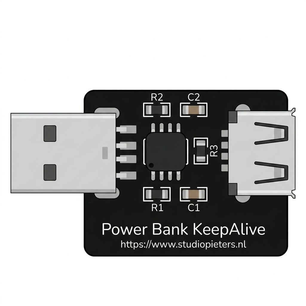
The Power Bank KeepAlive USB Female to USB Male adapter is a specialized cable or adapter designed to maintain a continuous power connection between a power bank and a USB-powered device. Unlike standard USB cables, this component ensures that the power bank does not automatically shut off when the connected device enters a low-power or standby mode. This feature is particularly useful for devices that require uninterrupted power, such as microcontrollers, IoT devices, or low-power sensors.
Explore Projects Built with Power Bank KeepAlive USB female to USB male


Explore Projects Built with Power Bank KeepAlive USB female to USB male
Common Applications and Use Cases
- Microcontroller Projects: Ensures uninterrupted power supply to Arduino, Raspberry Pi, or similar devices.
- IoT Devices: Keeps smart home devices or sensors powered without interruptions.
- Low-Power Devices: Prevents power banks from shutting off when powering devices with minimal current draw.
- Portable Electronics: Ideal for powering devices during travel or in remote locations.
Technical Specifications
The Power Bank KeepAlive USB Female to USB Male adapter is designed to work seamlessly with most power banks and USB-powered devices. Below are the key technical details:
General Specifications
| Parameter | Value |
|---|---|
| Input Connector | USB Female (Type-A) |
| Output Connector | USB Male (Type-A) |
| Voltage Range | 5V DC (standard USB voltage) |
| Current Capacity | Up to 2.4A (depending on power bank and device) |
| Cable Length (if applicable) | Typically 10-30 cm |
| Compatibility | USB 2.0 and USB 3.0 devices |
Pin Configuration and Descriptions
The USB connectors follow the standard USB pinout configuration:
USB Female (Input)
| Pin Number | Name | Description |
|---|---|---|
| 1 | VBUS | +5V DC power input |
| 2 | D- | Data line (-), not typically used |
| 3 | D+ | Data line (+), not typically used |
| 4 | GND | Ground |
USB Male (Output)
| Pin Number | Name | Description |
|---|---|---|
| 1 | VBUS | +5V DC power output |
| 2 | D- | Data line (-), not typically used |
| 3 | D+ | Data line (+), not typically used |
| 4 | GND | Ground |
Usage Instructions
How to Use the Component in a Circuit
- Connect the USB Female End: Plug the USB female connector into the power bank's output port.
- Connect the USB Male End: Attach the USB male connector to the device you want to power.
- Ensure Proper Connection: Verify that the device powers on and the power bank remains active.
- Optional: If the device enters a low-power mode, confirm that the power bank does not shut off. The KeepAlive feature should maintain the connection.
Important Considerations and Best Practices
- Power Bank Compatibility: Ensure the power bank supports the required current for your device. Some power banks may have a minimum current threshold for the KeepAlive feature to work effectively.
- Cable Length: Use a cable length appropriate for your setup to minimize voltage drop.
- Device Current Draw: If the connected device draws extremely low current, consider adding a small load resistor to prevent the power bank from shutting off.
- Avoid Overloading: Do not connect devices that exceed the current capacity of the power bank or the adapter.
Example: Using with an Arduino UNO
The Power Bank KeepAlive adapter can be used to power an Arduino UNO in portable projects. Below is an example of how to connect and use it:
- Connect the USB female end of the adapter to the power bank.
- Plug the USB male end into the Arduino UNO's USB port.
- Upload the following sample code to the Arduino UNO to simulate a low-power mode:
// Example code for Arduino UNO to simulate low-power operation
void setup() {
  pinMode(LED_BUILTIN, OUTPUT); // Set the built-in LED pin as output
}

void loop() {
  digitalWrite(LED_BUILTIN, HIGH); // Turn the LED on
  delay(1000);                     // Wait for 1 second
  digitalWrite(LED_BUILTIN, LOW);  // Turn the LED off
  delay(10000);                    // Wait for 10 seconds (simulate low power)
}
This code toggles the built-in LED on and off, with a long delay to simulate low-power operation. The KeepAlive adapter ensures the power bank remains active during the delay.
Troubleshooting and FAQs
Common Issues and Solutions
Power Bank Shuts Off Unexpectedly
- Cause: The connected device draws too little current.
- Solution: Add a small load resistor (e.g., 100Ω, 1/4W) in parallel with the device to increase the current draw slightly.
Device Does Not Power On
- Cause: Loose connection or insufficient power from the power bank.
- Solution: Check all connections and ensure the power bank can supply the required current.
Adapter Overheats
- Cause: Device exceeds the current capacity of the adapter.
- Solution: Use a device with lower power requirements or a higher-capacity adapter.
Power Bank Drains Quickly
- Cause: High current draw from the connected device or additional load.
- Solution: Use a power bank with a higher capacity or reduce the load.
FAQs
Q: Can this adapter be used with USB-C power banks?
A: Yes, but you may need a USB-C to USB-A adapter to connect the USB female end to the USB-C port.
Q: Does this adapter support data transfer?
A: No, this adapter is designed for power delivery only and does not support data transfer.
Q: Can I use this adapter with a fast-charging power bank?
A: Yes, but the adapter itself does not support fast-charging protocols. It will deliver standard 5V power.
Q: Is this adapter compatible with all USB devices?
A: It is compatible with most USB-powered devices, but ensure the device's power requirements match the power bank's output.