How to Use eNod4: Examples, Pinouts, and Specs
Introduction
The eNod4 is a compact, low-power microcontroller developed by Scaime (Part ID: T-DI00-A00-SC). It is specifically designed for IoT (Internet of Things) applications, offering built-in Wi-Fi connectivity and multiple GPIO (General Purpose Input/Output) pins for seamless interfacing with a wide range of sensors and actuators. Its small form factor and energy-efficient design make it an ideal choice for smart devices, home automation, industrial monitoring, and other IoT-based solutions.
Explore Projects Built with eNod4
Explore Projects Built with eNod4
Common Applications
- Smart home devices (e.g., smart thermostats, lighting systems)
- Industrial automation and monitoring
- Environmental sensing and data logging
- Wearable technology
- Remote control and telemetry systems
Technical Specifications
Key Technical Details
| Parameter | Specification |
|---|---|
| Microcontroller Core | 32-bit ARM Cortex-M4 |
| Operating Voltage | 3.3V |
| Wi-Fi Connectivity | IEEE 802.11 b/g/n |
| GPIO Pins | 16 (configurable as digital or analog) |
| ADC Resolution | 12-bit |
| Flash Memory | 512 KB |
| RAM | 128 KB |
| Communication Interfaces | UART, I2C, SPI |
| Power Consumption | 50 mW (typical) |
| Operating Temperature | -40°C to +85°C |
| Dimensions | 25mm x 20mm x 5mm |
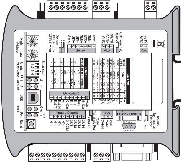
Pin Configuration and Descriptions
The eNod4 features a 16-pin layout, as detailed in the table below:
| Pin Number | Pin Name | Description |
|---|---|---|
| 1 | VCC | Power supply input (3.3V) |
| 2 | GND | Ground |
| 3 | GPIO0 | General-purpose I/O pin (digital/analog) |
| 4 | GPIO1 | General-purpose I/O pin (digital/analog) |
| 5 | GPIO2 | General-purpose I/O pin (digital/analog) |
| 6 | GPIO3 | General-purpose I/O pin (digital/analog) |
| 7 | GPIO4 | General-purpose I/O pin (digital/analog) |
| 8 | GPIO5 | General-purpose I/O pin (digital/analog) |
| 9 | GPIO6 | General-purpose I/O pin (digital/analog) |
| 10 | GPIO7 | General-purpose I/O pin (digital/analog) |
| 11 | TX | UART Transmit |
| 12 | RX | UART Receive |
| 13 | SCL | I2C Clock |
| 14 | SDA | I2C Data |
| 15 | SPI_CLK | SPI Clock |
| 16 | SPI_MOSI | SPI Master Out Slave In |
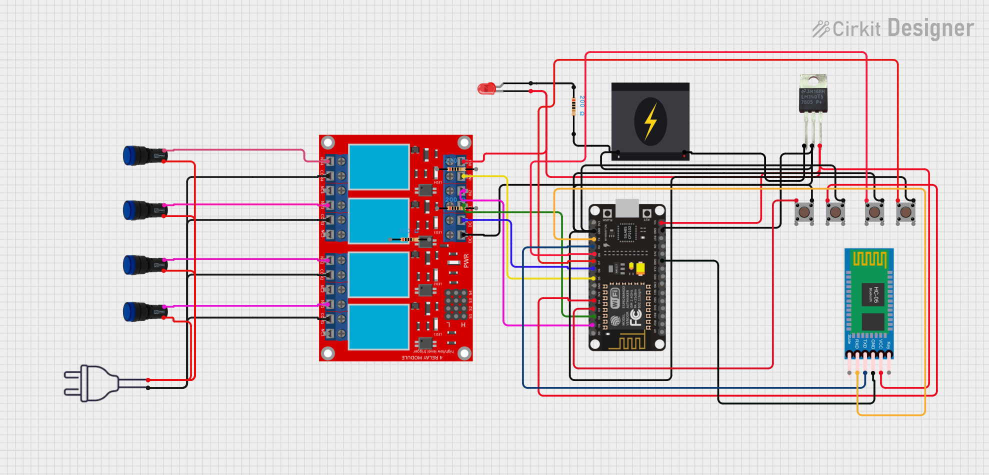
Usage Instructions
How to Use the eNod4 in a Circuit
- Power Supply: Connect the VCC pin to a 3.3V power source and the GND pin to ground.
- GPIO Configuration: Use the GPIO pins to interface with sensors, actuators, or other peripherals. Configure the pins as digital or analog inputs/outputs as required.
- Wi-Fi Setup: Use the built-in Wi-Fi module to connect the eNod4 to a wireless network for IoT applications.
- Communication Interfaces: Utilize UART, I2C, or SPI for communication with other devices or microcontrollers.
Important Considerations
- Ensure the power supply voltage does not exceed 3.3V to avoid damaging the component.
- Use appropriate pull-up or pull-down resistors for GPIO pins when necessary.
- For stable Wi-Fi performance, avoid placing the eNod4 near sources of electromagnetic interference.
- When using the ADC, ensure the input voltage does not exceed the reference voltage (3.3V).
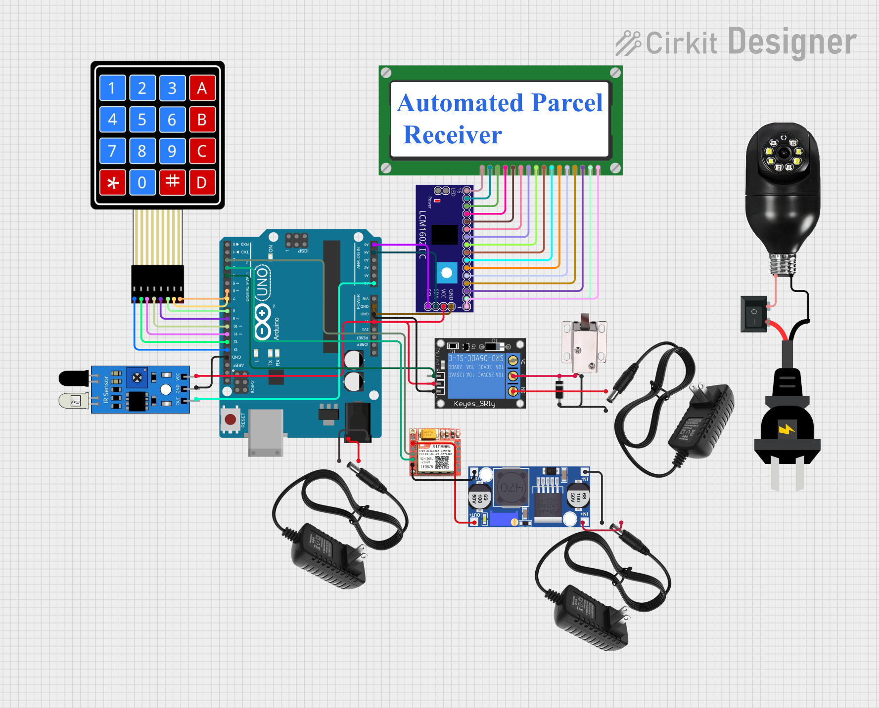
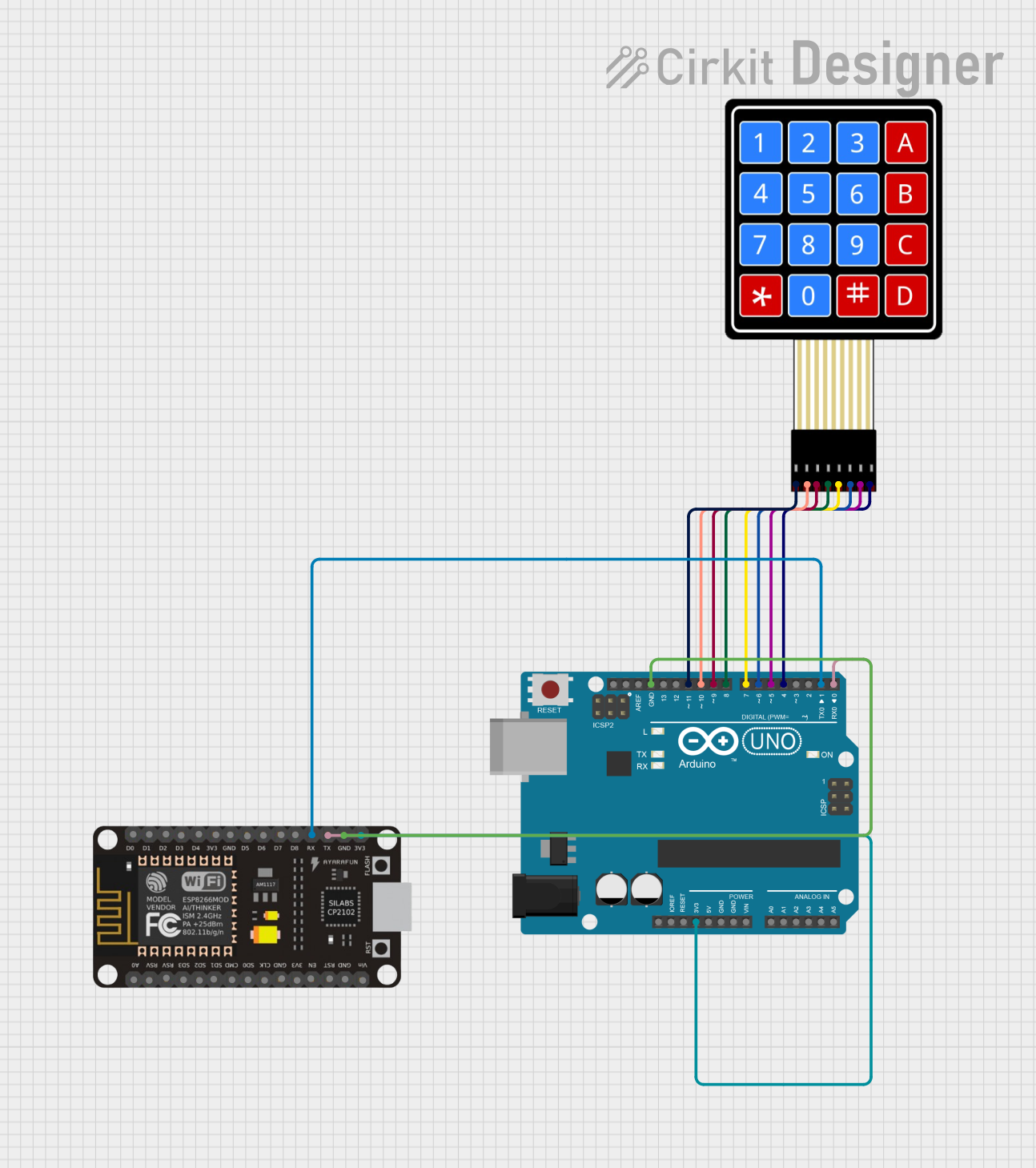
Example: Connecting eNod4 to an Arduino UNO
The eNod4 can be connected to an Arduino UNO via UART for communication. Below is an example Arduino sketch to send data to the eNod4:
// Example: Sending data to eNod4 via UART
// Ensure the eNod4's TX pin is connected to Arduino's RX pin (pin 0)
// and the eNod4's RX pin is connected to Arduino's TX pin (pin 1).

void setup() {
  Serial.begin(9600); // Initialize UART communication at 9600 baud rate
  delay(1000);        // Wait for eNod4 to initialize
}

void loop() {
  Serial.println("Hello, eNod4!"); // Send a message to the eNod4
  delay(1000);                     // Wait 1 second before sending again
}
Troubleshooting and FAQs
Common Issues and Solutions
eNod4 Not Powering On
- Cause: Insufficient or incorrect power supply.
- Solution: Ensure the VCC pin is supplied with 3.3V and the GND pin is properly connected.
Wi-Fi Connection Fails
- Cause: Incorrect network credentials or interference.
- Solution: Double-check the SSID and password. Ensure the eNod4 is within range of the Wi-Fi router.
GPIO Pins Not Responding
- Cause: Incorrect pin configuration or missing pull-up/pull-down resistors.
- Solution: Verify the pin mode (input/output) and add appropriate resistors if needed.
UART Communication Issues
- Cause: Mismatched baud rate or incorrect wiring.
- Solution: Ensure the baud rate matches on both devices and check the TX/RX connections.
FAQs
Q: Can the eNod4 operate at 5V?
A: No, the eNod4 is designed to operate at 3.3V. Using 5V may damage the component.Q: How many devices can be connected via I2C?
A: The eNod4 supports up to 127 devices on the I2C bus, depending on the address configuration.Q: Is the eNod4 compatible with 5V logic?
A: No, the eNod4 uses 3.3V logic. Use a level shifter if interfacing with 5V devices.Q: Can the eNod4 store data?
A: Yes, the eNod4 has 512 KB of flash memory for storing firmware and data.
This concludes the documentation for the eNod4. For further assistance, refer to the manufacturer's datasheet or contact Scaime support.