How to Use Adafruit Charlieplex 9x16 Warm White: Examples, Pinouts, and Specs
Introduction
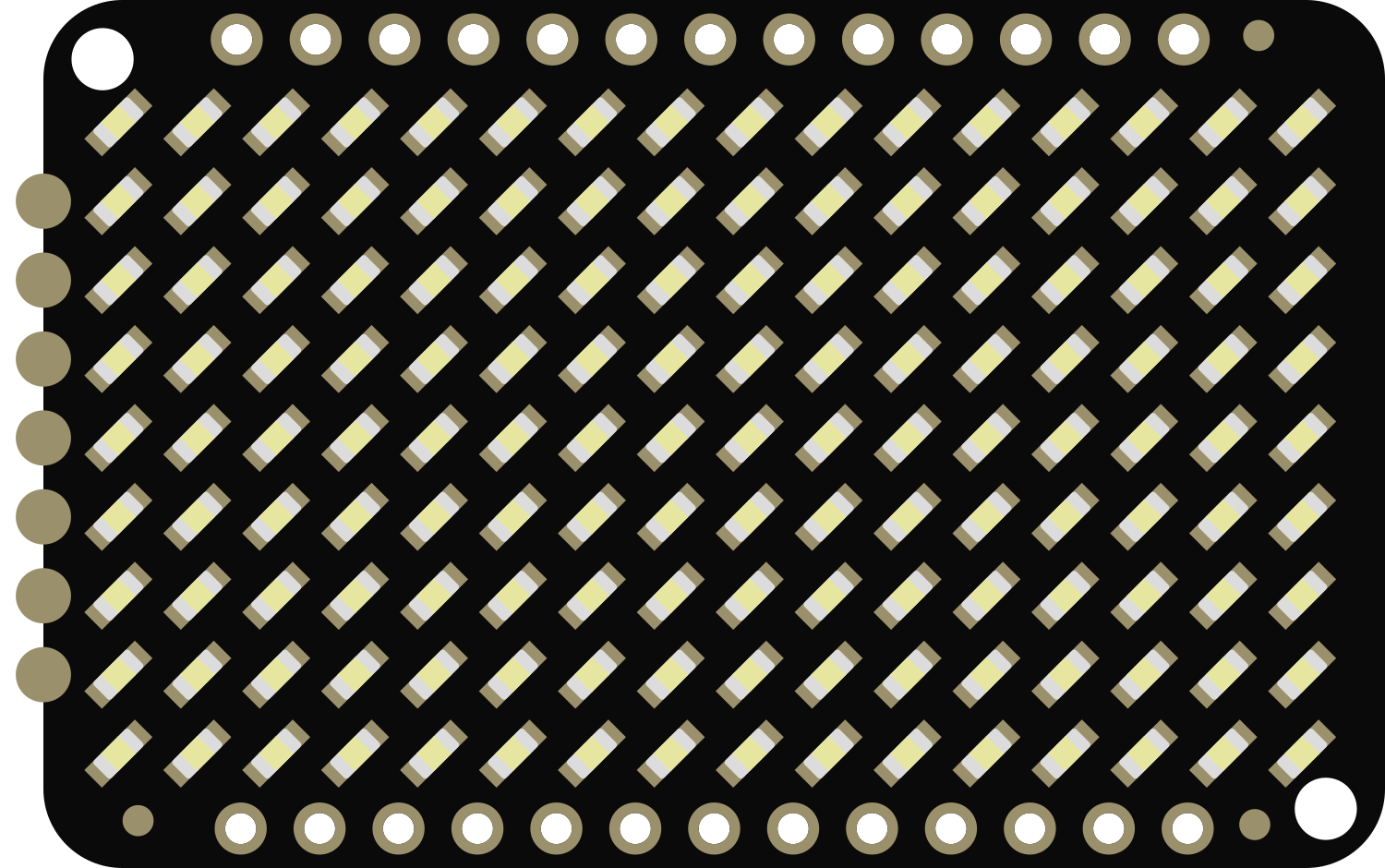
The Adafruit Charlieplex 9x16 Warm White LED Matrix is a compact and versatile display component that consists of 144 individually controllable warm white LEDs. This LED matrix utilizes the charlieplexing technique to enable control over each LED with a minimal number of microcontroller pins. It is ideal for creating eye-catching displays, indicators, and animations in projects where space is at a premium and power consumption needs to be minimized.
Explore Projects Built with Adafruit Charlieplex 9x16 Warm White
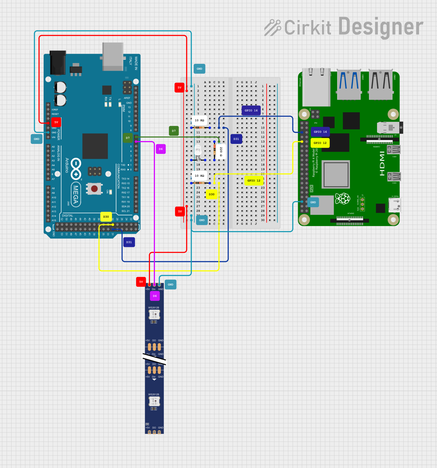
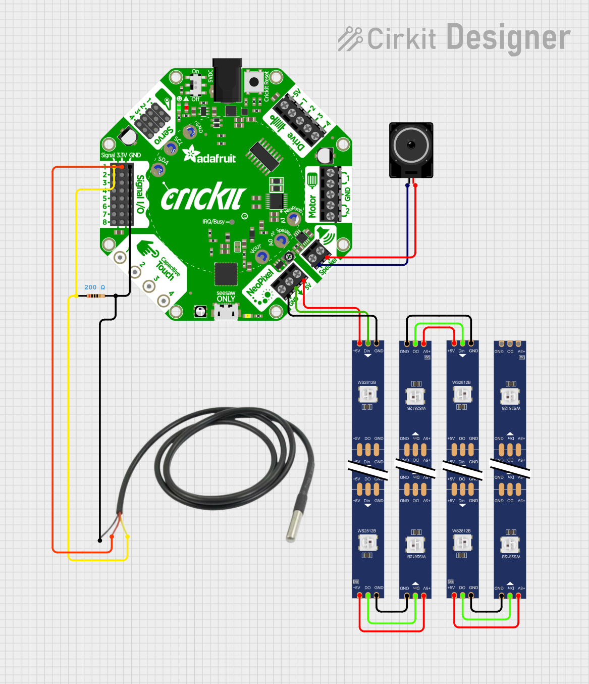


Explore Projects Built with Adafruit Charlieplex 9x16 Warm White
Common Applications and Use Cases
- Wearable electronics
- Small-scale message displays
- Decorative lighting
- User interface indicators
- Educational projects to demonstrate charlieplexing
Technical Specifications
Key Technical Details
- Operating Voltage: 3.3V - 5V
- Max Current (all LEDs on): ~350mA at 3.3V
- LED Color: Warm White
- Number of LEDs: 144
- Communication: I2C interface
Pin Configuration and Descriptions
| Pin Number | Name | Description |
|---|---|---|
| 1 | GND | Ground connection |
| 2 | VCC | Power supply (3.3V - 5V) |
| 3 | SDA | I2C Data line |
| 4 | SCL | I2C Clock line |
| 5 | ADDR | I2C Address selection (connect to GND or VCC) |
Usage Instructions
How to Use the Component in a Circuit
Power Connections: Connect the VCC pin to your power supply (3.3V - 5V) and the GND pin to the ground.
I2C Connections: Connect the SDA and SCL pins to the corresponding I2C data and clock lines on your microcontroller, such as an Arduino UNO.
Address Selection: The ADDR pin can be connected to GND or VCC to select between two I2C addresses. This allows for two matrices to be used on the same I2C bus.
Programming: Use the provided library and example code to control the LEDs.
Important Considerations and Best Practices
- Ensure that your power supply can handle the maximum current draw when all LEDs are on.
- Use pull-up resistors on the I2C lines if they are not included in your microcontroller board.
- Avoid powering the matrix from the microcontroller's 3.3V pin if using many LEDs at high brightness, as this may exceed the regulator's current capacity.
Example Code for Arduino UNO
#include <Wire.h>
#include <Adafruit_IS31FL3731.h>

// Create the LED driver object
Adafruit_IS31FL3731 matrix = Adafruit_IS31FL3731();

void setup() {
  Wire.begin(); // Start I2C
  if (!matrix.begin()) { // Initialize the LED driver
    Serial.println("IS31FL3731 not found");
    while (1);
  }
  Serial.println("IS31FL3731 found!");
}

void loop() {
  matrix.fillScreen(0); // Clear the display buffer

  // Draw a diagonal line
  for (int i = 0; i < 9; i++) {
    matrix.drawPixel(i, i, 50); // Set brightness to 50 out of 255
  }

  matrix.writeDisplay(); // Update the display with the buffer content
  delay(500);
}
Troubleshooting and FAQs
Common Issues
- LEDs Not Lighting Up: Ensure that the power supply is correctly connected and within the specified voltage range. Check the I2C connections and pull-up resistors.
- Dim LEDs: If the LEDs are dimmer than expected, check the power supply current capability and ensure it meets the maximum current requirements.
- Flickering LEDs: Flickering can occur if there is a loose connection or if the I2C bus is experiencing interference. Ensure all connections are secure and consider using shielded cables for long runs.
Solutions and Tips for Troubleshooting
- Double-check wiring against the pin configuration table.
- Use a multimeter to verify that the correct voltage is present at the VCC pin.
- Ensure that the correct I2C address is being used in your code.
- If using multiple matrices, ensure that each has a unique I2C address.
FAQs
Q: Can I use this matrix with a 3.3V microcontroller? A: Yes, the matrix can operate at 3.3V, but ensure that the I2C logic levels are compatible.
Q: How many of these matrices can I chain together? A: You can chain two matrices together on the same I2C bus by using different addresses set by the ADDR pin.
Q: What library should I use to control the matrix? A: The Adafruit_IS31FL3731 library is recommended for controlling the matrix with an Arduino.
Q: Can I control the brightness of individual LEDs? A: Yes, each LED's brightness can be controlled individually using the library's functions.