How to Use Motor with reducer: Examples, Pinouts, and Specs
Introduction
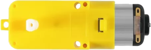
A motor with a reducer is an electromechanical device that converts electrical energy into mechanical energy. It features an integrated gear reduction mechanism, which increases torque while reducing the motor's output speed. This combination makes it ideal for applications requiring high torque at low speeds, such as robotics, conveyor systems, and industrial machinery. The reducer ensures precise control and efficient power transmission, making it a versatile component in various mechanical and automation systems.
Explore Projects Built with Motor with reducer

Explore Projects Built with Motor with reducer
Common Applications and Use Cases
- Robotics: For driving wheels or robotic arms with high torque requirements.
- Conveyor systems: To move heavy loads at controlled speeds.
- Industrial machinery: For applications requiring precise torque and speed control.
- Automated gates and doors: To ensure smooth and controlled movement.
- Electric vehicles: For efficient power delivery to wheels.
Technical Specifications
Below are the general technical specifications for a motor with a reducer. Note that specific values may vary depending on the model and manufacturer.
Key Technical Details
- Input Voltage: 6V to 24V DC (varies by model)
- Output Torque: Up to 50 Nm (depending on gear ratio and motor type)
- Gear Ratio: Common ratios include 10:1, 20:1, 50:1, and 100:1
- Output Speed: Typically ranges from 10 RPM to 500 RPM
- Motor Type: Brushed DC motor or brushless DC motor
- Current Consumption: 0.5A to 5A (depending on load and motor size)
- Shaft Diameter: 6mm to 12mm (varies by model)
- Operating Temperature: -10°C to 60°C
Pin Configuration and Descriptions
The motor with a reducer typically has two or more terminals for electrical connections. Below is a table describing the pin configuration for a common brushed DC motor with a reducer.
| Pin/Terminal | Description |
|---|---|
| V+ | Positive terminal for power input. |
| V- | Negative terminal for power input. |
| Encoder A | (Optional) Encoder signal A for speed and position feedback. |
| Encoder B | (Optional) Encoder signal B for speed and position feedback. |
For brushless DC motors with reducers, additional pins for hall sensors or control signals may be present.
Usage Instructions
How to Use the Component in a Circuit
- Power Supply: Connect the motor's V+ and V- terminals to a DC power supply or motor driver. Ensure the voltage matches the motor's rated input voltage.
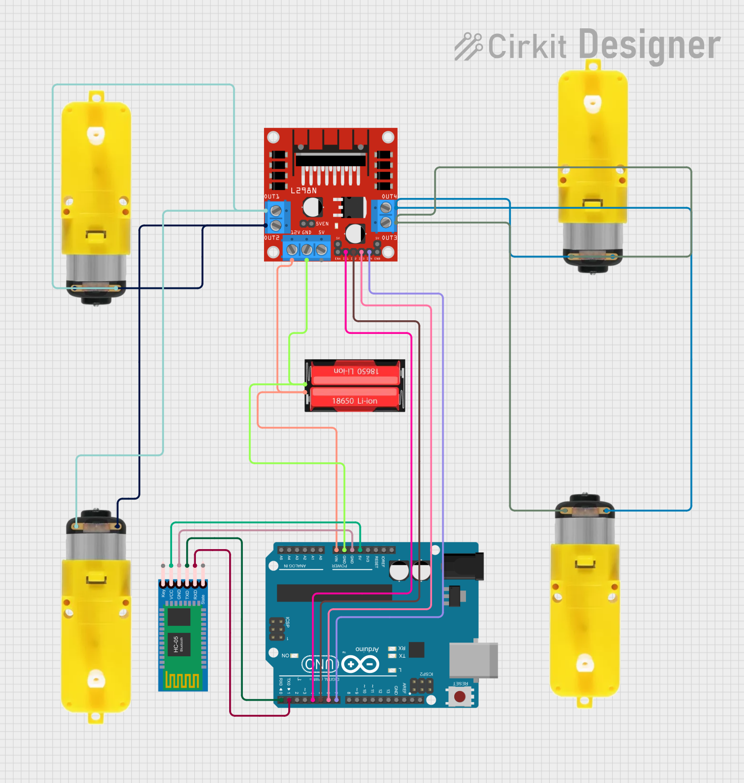
- Motor Driver: Use a motor driver or H-bridge circuit to control the motor's speed and direction. This is especially important for high-current motors.
- Gear Ratio Selection: Choose a motor with an appropriate gear ratio based on your application's torque and speed requirements.
- Mounting: Securely mount the motor and reducer to your mechanical system to prevent misalignment or vibration.
- Feedback (Optional): If the motor includes an encoder, connect the encoder pins to a microcontroller for speed and position feedback.
Important Considerations and Best Practices
- Avoid Overloading: Do not exceed the motor's rated torque or current to prevent damage.
- Heat Dissipation: Ensure proper ventilation or heat sinks to avoid overheating during prolonged use.
- Power Supply: Use a stable and adequately rated power supply to ensure consistent performance.
- Direction Control: Reverse the polarity of the V+ and V- terminals to change the motor's direction.
- Use with Arduino UNO: To control the motor with an Arduino UNO, use a motor driver like the L298N or L293D. Below is an example code snippet for controlling a motor with a reducer using an Arduino UNO.
// Example code to control a motor with reducer using Arduino UNO
// Motor driver connections: IN1 and IN2 control motor direction
// ENA controls motor speed (PWM signal)

#define IN1 8  // Motor driver IN1 pin connected to Arduino pin 8
#define IN2 9  // Motor driver IN2 pin connected to Arduino pin 9
#define ENA 10 // Motor driver ENA pin connected to Arduino pin 10 (PWM)

void setup() {
  pinMode(IN1, OUTPUT); // Set IN1 as output
  pinMode(IN2, OUTPUT); // Set IN2 as output
  pinMode(ENA, OUTPUT); // Set ENA as output
}

void loop() {
  // Rotate motor forward at 50% speed
  digitalWrite(IN1, HIGH); // Set IN1 high
  digitalWrite(IN2, LOW);  // Set IN2 low
  analogWrite(ENA, 128);   // Set ENA to 50% duty cycle (128/255)

  delay(2000); // Run motor for 2 seconds

  // Rotate motor backward at 75% speed
  digitalWrite(IN1, LOW);  // Set IN1 low
  digitalWrite(IN2, HIGH); // Set IN2 high
  analogWrite(ENA, 192);   // Set ENA to 75% duty cycle (192/255)

  delay(2000); // Run motor for 2 seconds

  // Stop the motor
  digitalWrite(IN1, LOW);  // Set IN1 low
  digitalWrite(IN2, LOW);  // Set IN2 low
  analogWrite(ENA, 0);     // Set ENA to 0% duty cycle (stop)

  delay(2000); // Wait for 2 seconds before repeating
}
Troubleshooting and FAQs
Common Issues Users Might Face
Motor Not Spinning:
- Check the power supply voltage and current rating.
- Verify the connections to the motor driver and ensure proper polarity.
- Ensure the motor driver is receiving control signals from the microcontroller.
Overheating:
- Reduce the load on the motor or use a motor with a higher torque rating.
- Ensure proper ventilation or add a heat sink to the motor.
Inconsistent Speed:
- Check for loose connections or damaged wires.
- If using an encoder, verify the encoder connections and signal integrity.
No Feedback from Encoder:
- Ensure the encoder pins are correctly connected to the microcontroller.
- Verify the microcontroller code for reading encoder signals.
Solutions and Tips for Troubleshooting
- Use a multimeter to check voltage and current at the motor terminals.
- Test the motor with a direct power supply to rule out issues with the motor driver.
- Inspect the gear reducer for mechanical obstructions or damage.
- If using an Arduino, verify the code and ensure the correct pins are defined.
By following this documentation, users can effectively integrate and troubleshoot a motor with a reducer in their projects.