How to Use SparkFun_Mini_GPS_Shield: Examples, Pinouts, and Specs
Introduction
The SparkFun Mini GPS Shield is an efficient and compact module designed to provide precise positioning and time data for various applications. It is equipped with a GPS receiver and is compatible with Arduino and other microcontrollers. The shield is particularly useful for projects such as GPS tracking systems, navigation devices, time synchronization, and geocaching.
Explore Projects Built with SparkFun_Mini_GPS_Shield

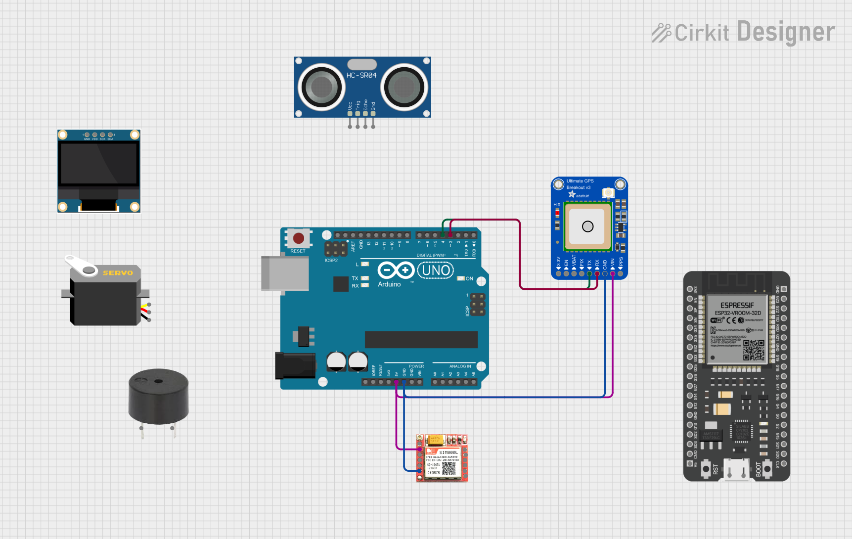
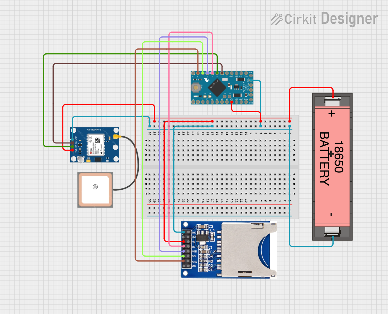
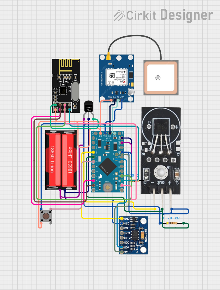
Explore Projects Built with SparkFun_Mini_GPS_Shield
Common Applications and Use Cases
- Personal tracking and navigation
- Geocaching and outdoor sports
- Fleet management and vehicle tracking
- Time synchronization for systems
- Data logging with location tagging
Technical Specifications
Key Technical Details
- Operating Voltage: 3.3V to 5V
- Power Consumption: 25mA (typical)
- Communication: UART (default) / SPI (optional)
- Update Rate: 1Hz (default), up to 10Hz
- Sensitivity: -165 dBm tracking, -148 dBm acquisition
- Time to First Fix: 29s (cold start), 1s (hot start)
- Operating Temperature: -40°C to 85°C
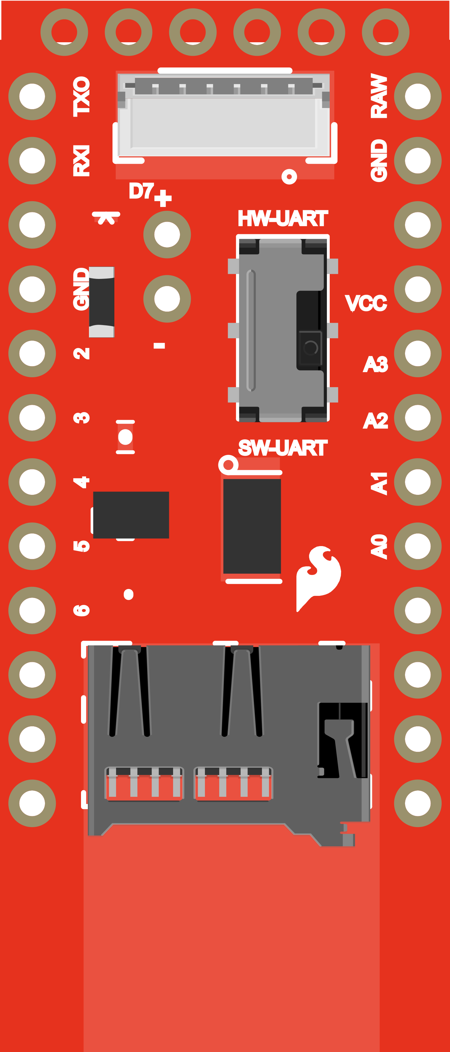
Pin Configuration and Descriptions
| Pin Number | Name | Description |
|---|---|---|
| 1 | VCC | Power supply (3.3V to 5V) |
| 2 | GND | Ground connection |
| 3 | TX | UART transmit (connect to RX of microcontroller) |
| 4 | RX | UART receive (connect to TX of microcontroller) |
| 5 | SCK | SPI Clock |
| 6 | MISO | SPI Master In Slave Out |
| 7 | MOSI | SPI Master Out Slave In |
| 8 | CS | SPI Chip Select |
Usage Instructions
How to Use the Component in a Circuit
- Powering the Shield: Connect the VCC pin to a 3.3V or 5V power supply and the GND pin to the ground.
- Communication Setup: For UART, connect the TX pin of the shield to the RX pin of your microcontroller and the RX pin to the TX pin. For SPI, connect SCK, MISO, MOSI, and CS to the corresponding SPI pins on your microcontroller.
- Antenna Connection: Ensure that the GPS antenna is securely connected to the shield for optimal signal reception.
- Programming: Upload the appropriate code to your microcontroller to start receiving GPS data.
Important Considerations and Best Practices
- Ensure that the GPS shield has a clear view of the sky for better satellite reception.
- Avoid placing the shield near devices that emit RF noise, as this can interfere with GPS signals.
- Use a level shifter if you are interfacing with a 5V microcontroller to protect the 3.3V logic levels of the GPS module.
- For faster position locks, enable the GPS module to have periodic updates even when not in active use.
Troubleshooting and FAQs
Common Issues Users Might Face
- No GPS Fix: Ensure clear sky visibility and check antenna connections.
- Garbled Data: Verify baud rate settings and cable connections between the shield and microcontroller.
- Intermittent Signal: Avoid placing the shield near devices that can cause RF interference.
Solutions and Tips for Troubleshooting
- No GPS Fix: Wait for a longer period, as cold starts can take up to 29 seconds.
- Garbled Data: Double-check the UART/SPI configuration and ensure that the correct communication protocol is selected.
- Intermittent Signal: Relocate the shield to a position with less interference or shield it using RF shielding techniques.
FAQs
Q: Can I use the Mini GPS Shield with a 5V Arduino? A: Yes, but ensure that you use a level shifter for the data lines to protect the 3.3V logic of the GPS module.
Q: How can I increase the update rate? A: The update rate can be configured using commands sent to the GPS module. Refer to the module's datasheet for the specific commands.
Q: What is the accuracy of the GPS module? A: The typical accuracy is within 2.5 meters under open-sky conditions.
Example Code for Arduino UNO
#include <SoftwareSerial.h>

// The serial connection to the GPS module
SoftwareSerial gpsSerial(4, 3); // RX, TX

void setup() {
  // Start the serial communication
  Serial.begin(9600);
  gpsSerial.begin(9600); // Default baud rate of the GPS module
  Serial.println("GPS Shield Test");
}

void loop() {
  // Check if data is available from the GPS module
  if (gpsSerial.available()) {
    // Forward the data to the computer
    Serial.write(gpsSerial.read());
  }
}
Note: This example uses software serial to communicate with the GPS module. The GPS module's TX pin is connected to digital pin 4 (RX on Arduino) and RX pin to digital pin 3 (TX on Arduino). Adjust the pin numbers as needed for your specific setup.