Cirkit Designer Logo
Cirkit Designer
Your all-in-one circuit design IDE
Home / 
Component Documentation

How to Use CT Close: Examples, Pinouts, and Specs

Image of CT Close
Cirkit Designer LogoDesign with CT Close in Cirkit Designer

Introduction

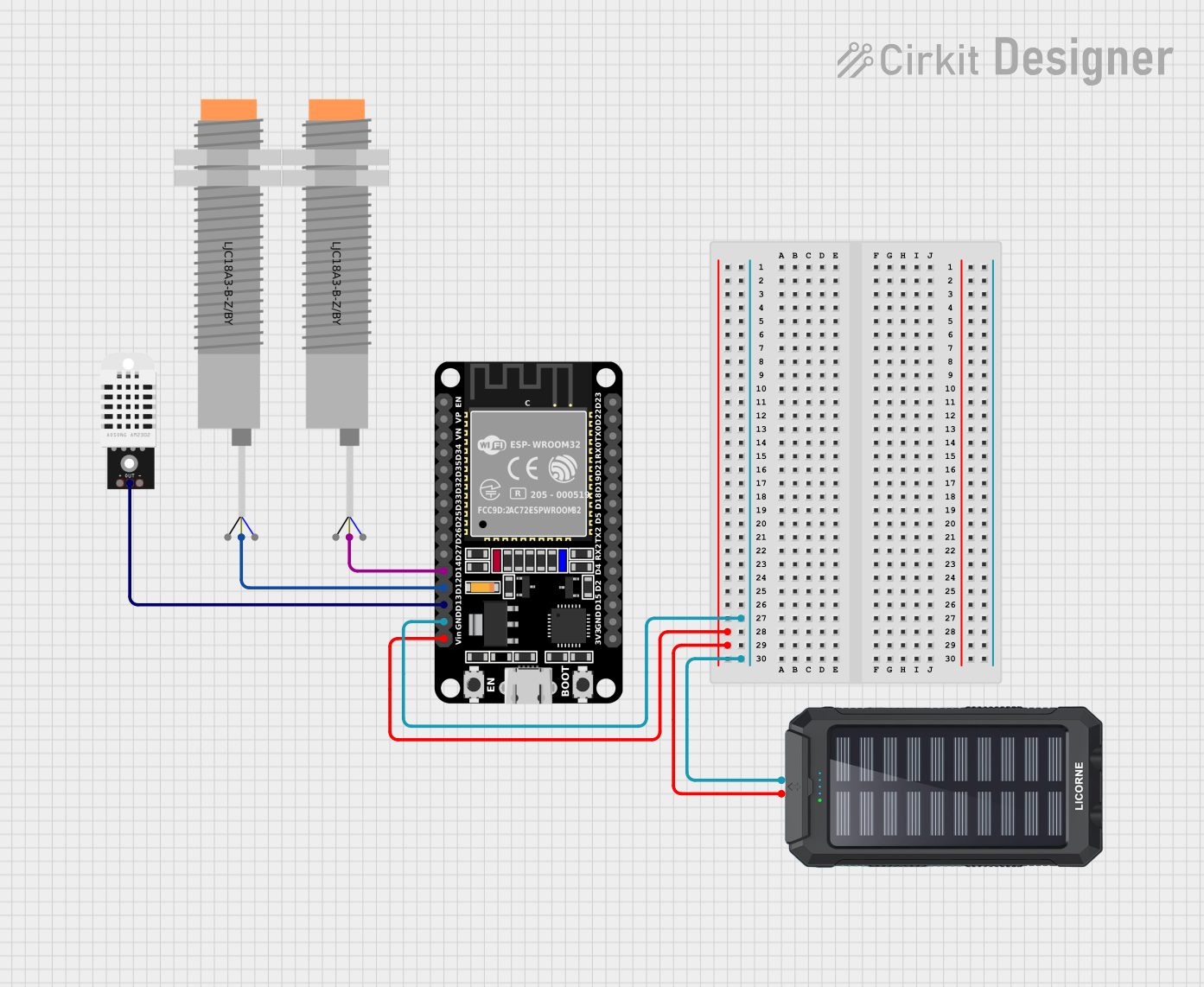
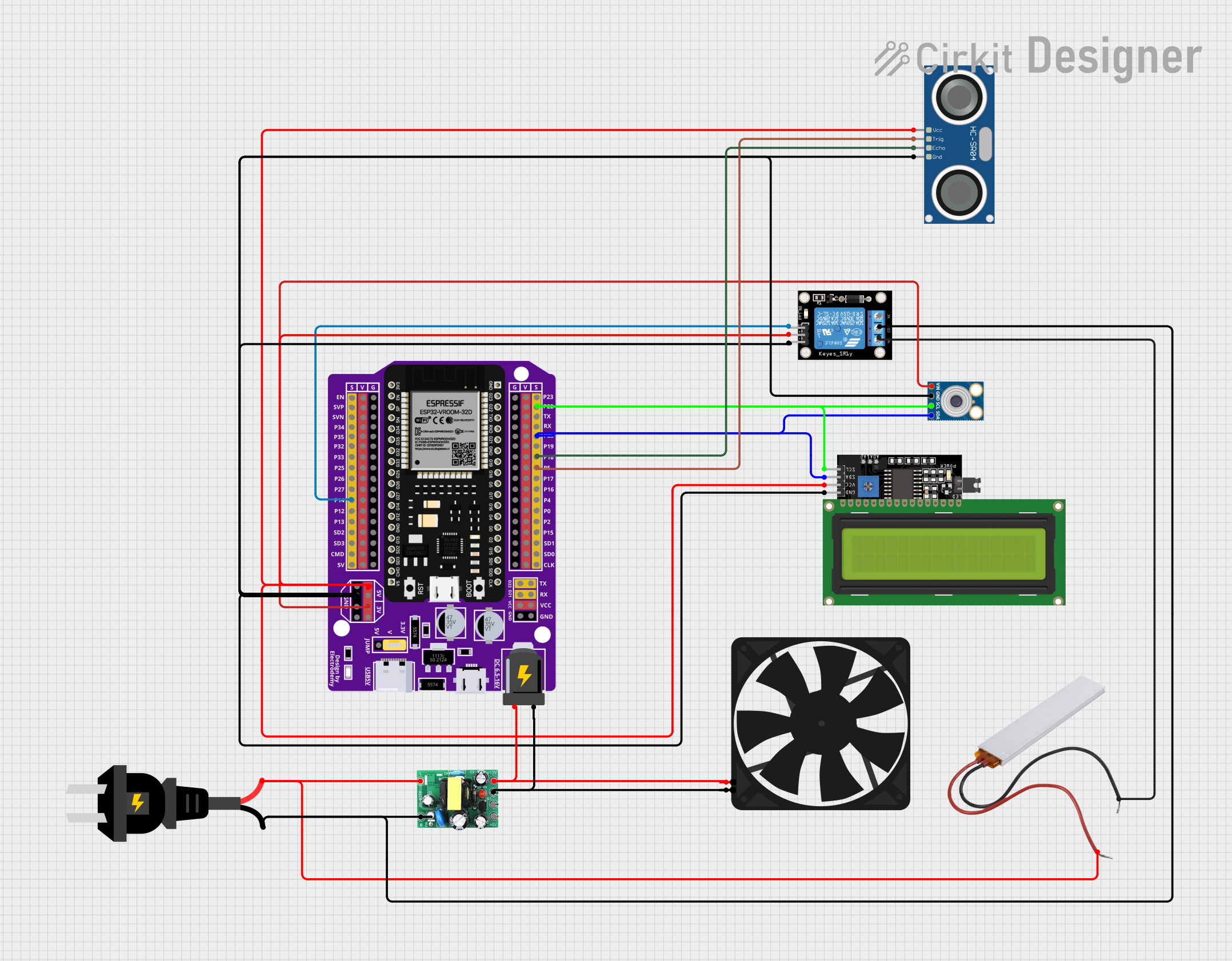
The CT Close, manufactured by 1 with part ID 2, is a switch or relay designed to close the circuit in a current transformer (CT). This action allows current to flow through the secondary winding, enabling accurate measurement or protection of electrical systems. CT Close components are essential in power monitoring, energy management, and protection systems in various industrial and commercial applications.

Explore Projects Built with CT Close

Use Cirkit Designer to design, explore, and prototype these projects online. Some projects support real-time simulation. Click "Open Project" to start designing instantly!
Dual RTC DS3231 Synchronization with Glyph C3 Microcontroller
Image of DS: A project utilizing CT Close in a practical application
This circuit integrates two RTC DS3231 real-time clock modules with a Glyph C3 microcontroller. The RTC modules are connected to the microcontroller via I2C communication protocol, using the SCL and SDA lines for clock and data respectively. Both RTC modules and the microcontroller share a common power supply (3V3) and ground (GND), indicating that they operate at the same voltage level.
Cirkit Designer LogoOpen Project in Cirkit Designer
ESP32-Based Automatic Passenger Counter and Temperature Sensor with Wi-Fi Connectivity
Image of Embedded Circuit: A project utilizing CT Close in a practical application
This circuit is an automatic passenger counter and temperature sensor system powered by a solar charger. It uses an ESP32 microcontroller to interface with two capacitive proximity sensors for counting passengers and a DHT22 sensor for monitoring temperature and humidity, with data being sent to a Blynk mobile app and Google Sheets for real-time tracking and logging.
Cirkit Designer LogoOpen Project in Cirkit Designer
PLC-Controlled Power Window System with Infrared Sensing and Relay Module
Image of wiring FYP: A project utilizing CT Close in a practical application
This circuit is designed to control a motorized window system using a PLC (Programmable Logic Controller) and an array of sensors and switches. It includes power supplies for 12V and 24V DC, an MCB (Miniature Circuit Breaker) for protection, and a relay module interfaced with an Arduino for additional control logic. The PLC manages inputs from pushbuttons, a 3-position switch, infrared proximity sensors, and an emergency stop, and it controls outputs such as the motor speed controller, lamps, and solenoid valves.
Cirkit Designer LogoOpen Project in Cirkit Designer
ESP32-Based Smart Environment Controller with Relay and Sensor Integration
Image of thesis: A project utilizing CT Close in a practical application
This circuit features an ESP32 microcontroller interfaced with various sensors and modules, including an MLX90614 infrared temperature sensor, an HC-SR04 ultrasonic distance sensor, and an LCD display for output. A KY-019 relay module is controlled by the ESP32 to switch an AC source, with a PTC for circuit protection. Additionally, an AC-to-DC converter powers the ESP32 and a fan, indicating the circuit may be used for temperature-based control applications with visual feedback and actuation capabilities.
Cirkit Designer LogoOpen Project in Cirkit Designer

Explore Projects Built with CT Close

Use Cirkit Designer to design, explore, and prototype these projects online. Some projects support real-time simulation. Click "Open Project" to start designing instantly!
Image of DS: A project utilizing CT Close in a practical application
Dual RTC DS3231 Synchronization with Glyph C3 Microcontroller
This circuit integrates two RTC DS3231 real-time clock modules with a Glyph C3 microcontroller. The RTC modules are connected to the microcontroller via I2C communication protocol, using the SCL and SDA lines for clock and data respectively. Both RTC modules and the microcontroller share a common power supply (3V3) and ground (GND), indicating that they operate at the same voltage level.
Cirkit Designer LogoOpen Project in Cirkit Designer
Image of Embedded Circuit: A project utilizing CT Close in a practical application
ESP32-Based Automatic Passenger Counter and Temperature Sensor with Wi-Fi Connectivity
This circuit is an automatic passenger counter and temperature sensor system powered by a solar charger. It uses an ESP32 microcontroller to interface with two capacitive proximity sensors for counting passengers and a DHT22 sensor for monitoring temperature and humidity, with data being sent to a Blynk mobile app and Google Sheets for real-time tracking and logging.
Cirkit Designer LogoOpen Project in Cirkit Designer
Image of wiring FYP: A project utilizing CT Close in a practical application
PLC-Controlled Power Window System with Infrared Sensing and Relay Module
This circuit is designed to control a motorized window system using a PLC (Programmable Logic Controller) and an array of sensors and switches. It includes power supplies for 12V and 24V DC, an MCB (Miniature Circuit Breaker) for protection, and a relay module interfaced with an Arduino for additional control logic. The PLC manages inputs from pushbuttons, a 3-position switch, infrared proximity sensors, and an emergency stop, and it controls outputs such as the motor speed controller, lamps, and solenoid valves.
Cirkit Designer LogoOpen Project in Cirkit Designer
Image of thesis: A project utilizing CT Close in a practical application
ESP32-Based Smart Environment Controller with Relay and Sensor Integration
This circuit features an ESP32 microcontroller interfaced with various sensors and modules, including an MLX90614 infrared temperature sensor, an HC-SR04 ultrasonic distance sensor, and an LCD display for output. A KY-019 relay module is controlled by the ESP32 to switch an AC source, with a PTC for circuit protection. Additionally, an AC-to-DC converter powers the ESP32 and a fan, indicating the circuit may be used for temperature-based control applications with visual feedback and actuation capabilities.
Cirkit Designer LogoOpen Project in Cirkit Designer

Technical Specifications

Key Technical Details

Parameter Value
Manufacturer 1
Part ID 2
Voltage Rating 24V DC
Current Rating 10A
Power Rating 240W
Contact Resistance ≤ 100 mΩ
Insulation Resistance ≥ 1000 MΩ @ 500V DC
Operating Temperature -40°C to +85°C
Mechanical Life 10^6 operations
Electrical Life 10^5 operations

Pin Configuration and Descriptions

Pin Number Pin Name Description
1 COM Common terminal
2 NO Normally Open contact
3 NC Normally Closed contact
4 Coil+ Positive terminal of the relay coil
5 Coil- Negative terminal of the relay coil

Usage Instructions

How to Use the Component in a Circuit

  1. Power Supply Connection: Connect the positive terminal of the power supply to the Coil+ pin and the negative terminal to the Coil- pin to energize the relay coil.
  2. Load Connection: Connect the load between the COM and NO pins if you want the circuit to be closed when the relay is energized. Alternatively, connect the load between the COM and NC pins if you want the circuit to be closed when the relay is de-energized.
  3. Current Transformer Connection: Connect the secondary winding of the current transformer to the COM and NO pins to allow current flow through the secondary winding when the relay is energized.

Important Considerations and Best Practices

  • Voltage and Current Ratings: Ensure that the voltage and current ratings of the CT Close match the requirements of your application to prevent damage to the component or the circuit.
  • Proper Insulation: Maintain proper insulation between the high voltage and low voltage sides of the circuit to ensure safety and prevent electrical hazards.
  • Avoid Overloading: Do not exceed the specified current rating to avoid overheating and potential failure of the relay.
  • Regular Maintenance: Periodically check the contact resistance and insulation resistance to ensure reliable operation and longevity of the component.

Troubleshooting and FAQs

Common Issues Users Might Face

  1. Relay Not Energizing: If the relay does not energize, check the power supply connections to the Coil+ and Coil- pins. Ensure that the voltage is within the specified range.
  2. No Current Flow Through Secondary Winding: If there is no current flow through the secondary winding of the CT, verify the connections between the COM and NO pins. Ensure that the relay is properly energized.
  3. High Contact Resistance: If the contact resistance is higher than specified, clean the contacts and check for any signs of wear or damage. Replace the relay if necessary.

Solutions and Tips for Troubleshooting

  • Check Power Supply: Ensure that the power supply voltage is stable and within the specified range for the relay coil.
  • Verify Connections: Double-check all connections to ensure they are secure and correctly wired.
  • Inspect Relay Contacts: Periodically inspect the relay contacts for signs of wear, corrosion, or damage. Clean or replace the relay if needed.
  • Test Insulation Resistance: Use a megohmmeter to test the insulation resistance between the relay contacts and the coil. Ensure it meets the specified value.

Example Code for Arduino UNO

Below is an example code to control the CT Close relay using an Arduino UNO:

// Define the pin connected to the relay coil
const int relayPin = 7;

void setup() {
  // Initialize the relay pin as an output
  pinMode(relayPin, OUTPUT);
}

void loop() {
  // Energize the relay to close the circuit
  digitalWrite(relayPin, HIGH);
  delay(5000); // Keep the relay energized for 5 seconds

  // De-energize the relay to open the circuit
  digitalWrite(relayPin, LOW);
  delay(5000); // Keep the relay de-energized for 5 seconds
}

This code will energize the relay for 5 seconds, allowing current to flow through the secondary winding of the CT, and then de-energize it for 5 seconds, stopping the current flow. Adjust the delay values as needed for your specific application.

By following this documentation, users can effectively utilize the CT Close component in their circuits, ensuring accurate current measurement and protection in various electrical systems.