How to Use 3.3V PWM Signal to 0-10V Voltage Converter D/A Digital-Analog PLC Module: Examples, Pinouts, and Specs
Introduction
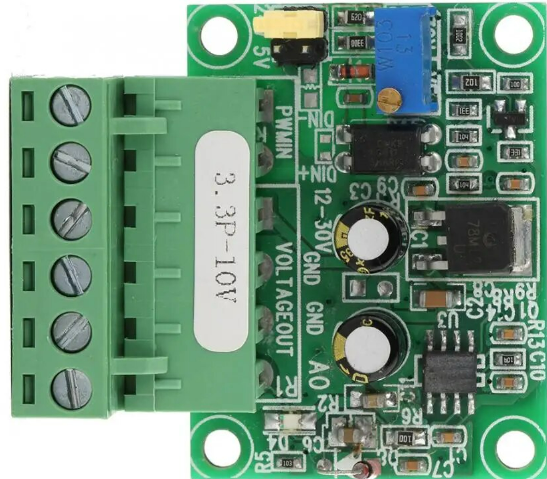
The 3.3V PWM Signal to 0-10V Voltage Converter is an electronic module designed to interface digital systems with analog control devices. It converts a 3.3V Pulse Width Modulation (PWM) signal into a proportional 0-10V analog voltage output. This module is particularly useful in industrial automation applications where microcontrollers, such as an Arduino, need to control devices that require a 0-10V input, such as dimmers, speed controllers, or other types of variable signal inputs.
Explore Projects Built with 3.3V PWM Signal to 0-10V Voltage Converter D/A Digital-Analog PLC Module


Explore Projects Built with 3.3V PWM Signal to 0-10V Voltage Converter D/A Digital-Analog PLC Module
Common Applications
- Industrial automation systems
- Motor speed control
- LED dimming control
- Variable frequency drives (VFD)
- Analog input modules for PLCs
Technical Specifications
Key Technical Details
- Input Voltage (Vcc): 3.3V to 5V DC
- PWM Input Signal: 3.3V logic level
- Output Voltage Range: 0-10V DC
- Resolution: Dependent on PWM resolution
- Frequency Range: Typically 1kHz to 3kHz (PWM input)
- Conversion Efficiency: >90%
- Operating Temperature: -20°C to +60°C
Pin Configuration and Descriptions
| Pin Number | Pin Name | Description |
|---|---|---|
| 1 | Vcc | Power supply input (3.3V to 5V DC) |
| 2 | GND | Ground connection |
| 3 | PWM | PWM signal input (3.3V logic level) |
| 4 | Vout | Analog voltage output (0-10V) |
Usage Instructions
How to Use the Component in a Circuit
- Power Supply Connection: Connect the Vcc pin to a 3.3V or 5V power supply and the GND pin to the common ground of your system.
- PWM Signal Input: Connect the PWM pin to the PWM output of your microcontroller (e.g., an Arduino UNO).
- Analog Voltage Output: Connect the Vout pin to the device that requires the 0-10V input.
Important Considerations and Best Practices
- Ensure that the power supply voltage does not exceed the specified maximum for the module.
- The PWM input signal should match the logic level of the microcontroller (3.3V for this module).
- The frequency of the PWM signal should be within the specified range for optimal performance.
- Use a decoupling capacitor across the power supply pins if there is noise in the power supply.
- Avoid placing the module in environments with extreme temperatures or humidity.
Example Code for Arduino UNO
// Define the PWM pin
const int pwmPin = 3; // Use a PWM capable pin on the Arduino

void setup() {
  // Set the PWM pin as an output
  pinMode(pwmPin, OUTPUT);
}

void loop() {
  // Generate a PWM signal with a duty cycle ranging from 0 to 255
  for (int dutyCycle = 0; dutyCycle <= 255; dutyCycle++) {
    // Write the duty cycle to the PWM pin
    analogWrite(pwmPin, dutyCycle);
    // Wait for 10 milliseconds
    delay(10);
  }
}
Note: The above code will generate a PWM signal with a varying duty cycle, which will be converted to a corresponding 0-10V output by the module. The analogWrite function is used to output PWM on the specified pin.
Troubleshooting and FAQs
Common Issues
- No Output Voltage: Ensure that the module is properly powered and that the PWM signal is being generated by the microcontroller.
- Incorrect Output Voltage: Check if the PWM signal frequency and duty cycle are within the specified range. Also, verify the power supply voltage and connections.
- Unstable Output Voltage: Place a decoupling capacitor close to the power supply pins on the module to filter out noise.
Solutions and Tips for Troubleshooting
- Double-check all connections and ensure that the wiring is correct.
- Use an oscilloscope to verify the PWM signal's frequency and duty cycle.
- If the output is not linear or stable, consider adding a low-pass filter to smooth out the PWM signal.
FAQs
Q: Can I use a 5V PWM signal with this module? A: This module is designed for a 3.3V PWM signal. Using a 5V signal may damage the module or cause it to function improperly.
Q: What is the maximum frequency for the PWM input? A: The typical frequency range for the PWM input is 1kHz to 3kHz. Operating outside this range may result in inaccurate conversion.
Q: How do I calibrate the output voltage? A: Calibration can be done by adjusting the duty cycle of the PWM signal. A duty cycle of 0% should correspond to 0V output, and 100% to 10V output. Use a multimeter to measure and adjust accordingly.
Q: Is this module isolated? A: This documentation does not specify isolation. Typically, such modules are not isolated, and care should be taken to ensure that the ground is shared between the PWM source and the module.
For further assistance, consult the manufacturer's datasheet or contact technical support.