How to Use AC Light Dimmer: Examples, Pinouts, and Specs
AC Light Dimmer Documentation
1. Introduction
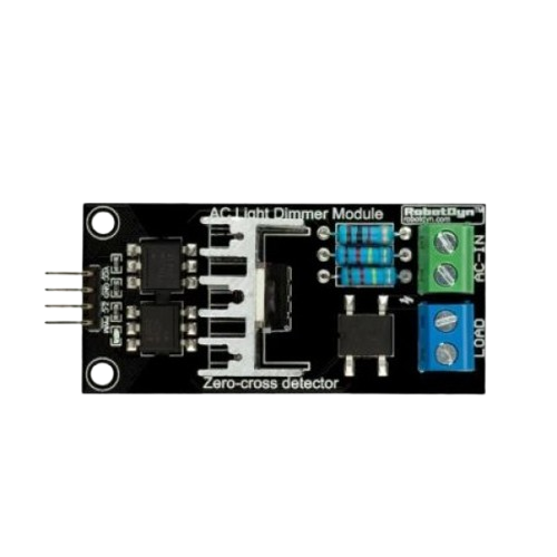
The AC Light Dimmer (Manufacturer: easy.ware, Part ID: Dimmer) is an electronic device designed to control the brightness of AC-powered light fixtures, such as incandescent and dimmable LED lights. By varying the voltage and current supplied to the light, the dimmer allows users to adjust the light intensity to suit their needs. This component is widely used in home automation, lighting control systems, and energy-saving applications.
Common Applications:
- Home Automation: Adjusting light levels for comfort and ambiance.
- Theatrical Lighting: Controlling stage lighting for performances.
- Energy Efficiency: Reducing power consumption by dimming lights.
- Smart Lighting Systems: Integration with microcontrollers like Arduino for automated control.
2. Technical Specifications
The following table outlines the key technical details of the easy.ware Dimmer:
| Parameter | Value |
|---|---|
| Operating Voltage | 110V - 240V AC |
| Maximum Load Current | 2A |
| Power Rating | Up to 400W |
| Control Voltage | 3.3V - 5V DC |
| Trigger Type | Zero-crossing detection |
| Isolation | Optocoupler-based isolation |
| Operating Temperature | -20°C to 70°C |
| Dimensions | 50mm x 30mm x 20mm |
Pin Configuration and Descriptions
| Pin Name | Type | Description |
|---|---|---|
| AC-IN | Input | Connects to the live (L) and neutral (N) wires of the AC power source. |
| AC-OUT | Output | Connects to the load (e.g., light bulb). |
| GND | Ground | Ground connection for the control circuit. |
| VCC | Power Input | 3.3V - 5V DC input for powering the control circuit. |
| PWM | Control Signal | Pulse Width Modulation (PWM) input for dimming control (from a microcontroller). |
3. Usage Instructions
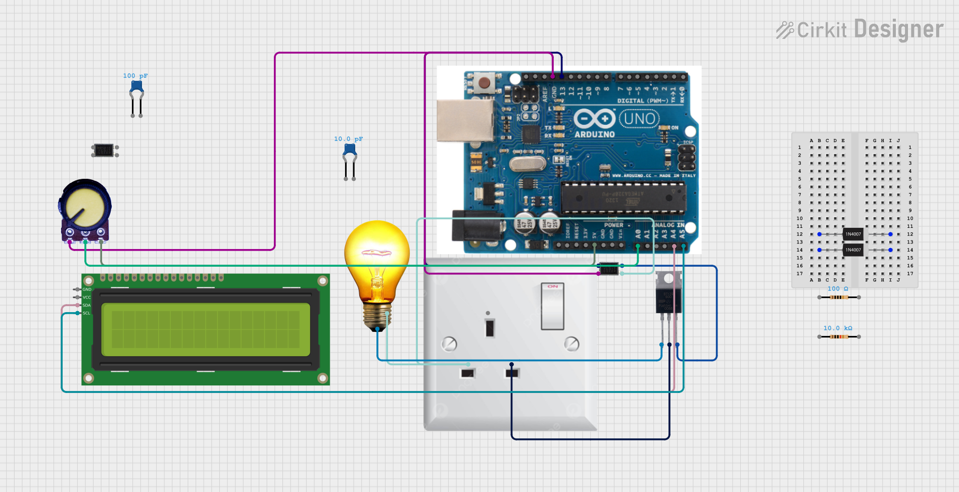
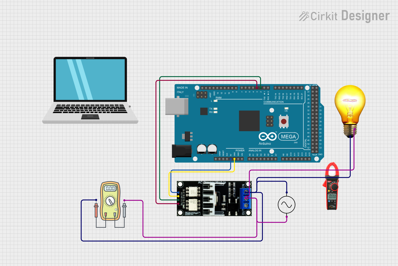
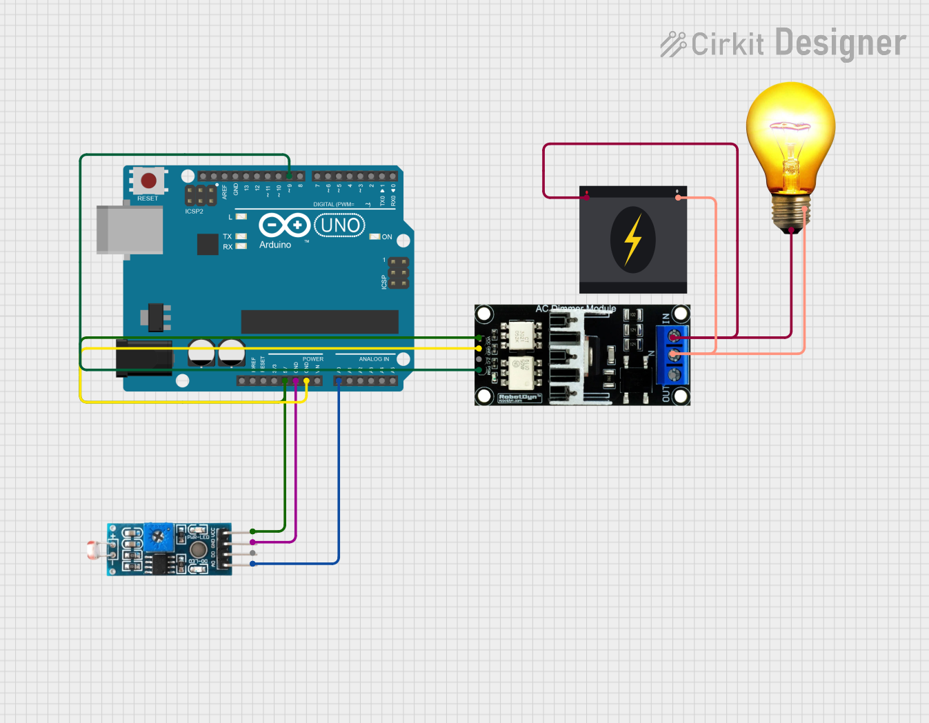
How to Use the AC Light Dimmer in a Circuit
- Safety First: Ensure the power supply is disconnected before wiring the dimmer. Handle AC connections with care.
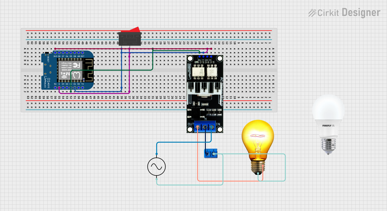
- Connect the AC Power:
- Connect the AC-IN pins to the live (L) and neutral (N) wires of the AC power source.
- Connect the AC-OUT pins to the load (e.g., an incandescent or dimmable LED light).
- Connect the Control Circuit:
- Connect the GND pin to the ground of your microcontroller (e.g., Arduino UNO).
- Connect the VCC pin to a 3.3V or 5V DC power source.
- Connect the PWM pin to a PWM-capable pin on your microcontroller.
- Programming the Microcontroller:
- Use a PWM signal to control the brightness of the light. A higher duty cycle increases brightness, while a lower duty cycle decreases it.
Important Considerations and Best Practices
- Isolation: The dimmer uses optocoupler-based isolation for safety. Ensure proper grounding to avoid electrical hazards.
- Load Compatibility: Only use the dimmer with compatible loads (e.g., dimmable LEDs or incandescent bulbs). Non-dimmable LEDs may flicker or malfunction.
- PWM Frequency: Use a PWM frequency of 50Hz or higher for smooth dimming.
- Heat Dissipation: Ensure adequate ventilation to prevent overheating, especially when operating near the maximum load.
4. Example Arduino Code
Below is an example of how to use the easy.ware Dimmer with an Arduino UNO to control the brightness of a light using a potentiometer.
// Example: Controlling AC Light Dimmer with Arduino UNO
// Manufacturer: easy.ware
// Part ID: Dimmer

const int pwmPin = 9;  // PWM pin connected to the dimmer's PWM input
const int potPin = A0; // Analog pin connected to the potentiometer

void setup() {
  pinMode(pwmPin, OUTPUT); // Set the PWM pin as an output
}

void loop() {
  int potValue = analogRead(potPin); // Read the potentiometer value (0-1023)

  // Map the potentiometer value to a PWM duty cycle (0-255)
  int pwmValue = map(potValue, 0, 1023, 0, 255);

  analogWrite(pwmPin, pwmValue); // Output the PWM signal to the dimmer

  delay(10); // Small delay for stability
}
Code Explanation:
- The potentiometer is used to adjust the brightness of the light.
- The
analogRead()function reads the potentiometer value, which is then mapped to a PWM duty cycle using themap()function. - The
analogWrite()function sends the PWM signal to the dimmer's control pin.
5. Troubleshooting and FAQs
Common Issues and Solutions
| Issue | Possible Cause | Solution |
|---|---|---|
| Light does not turn on | Incorrect wiring or loose connections | Double-check all connections, especially AC-IN and AC-OUT. |
| Light flickers | Incompatible load or incorrect PWM frequency | Use a dimmable light and ensure the PWM frequency is 50Hz or higher. |
| Dimmer overheats | Exceeding the maximum load rating | Ensure the load does not exceed 400W. Provide proper ventilation. |
| No response to PWM signal | Incorrect control voltage or wiring | Verify that the VCC and PWM pins are correctly connected to the microcontroller. |
Frequently Asked Questions (FAQs)
Can I use this dimmer with non-dimmable LED lights?
- No, non-dimmable LEDs may flicker or fail when used with this dimmer.
What happens if I exceed the maximum load rating?
- Exceeding the load rating can cause overheating, damage to the dimmer, or even fire hazards. Always stay within the specified limits.
Can I control multiple lights with one dimmer?
- Yes, as long as the total load does not exceed 400W.
Is the dimmer compatible with 3.3V microcontrollers like ESP32?
- Yes, the dimmer supports control voltages between 3.3V and 5V.
6. Safety Warnings
- Always disconnect the power supply before wiring or modifying the circuit.
- Handle AC connections with extreme caution to avoid electric shock.
- Do not exceed the specified load rating to prevent overheating or damage.
- Ensure proper insulation and grounding to avoid electrical hazards.
This documentation provides a comprehensive guide to using the easy.ware Dimmer safely and effectively. For further assistance, refer to the manufacturer's support resources.
Explore Projects Built with AC Light Dimmer
Explore Projects Built with AC Light Dimmer