Cirkit Designer Logo
Cirkit Designer
Your all-in-one circuit design IDE
Home / 
Component Documentation

How to Use Heltec T114: Examples, Pinouts, and Specs

Image of Heltec T114
Cirkit Designer LogoDesign with Heltec T114 in Cirkit Designer

Introduction

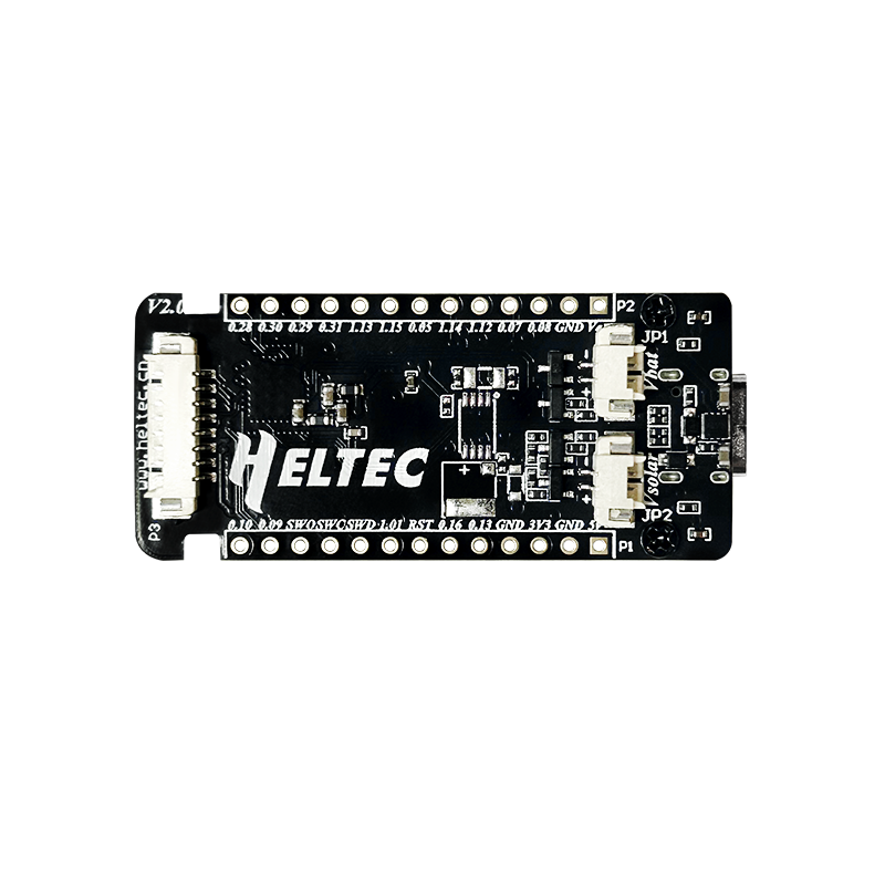
The Heltec T114 is a compact and versatile development board designed for Internet of Things (IoT) applications. Powered by the ESP32 microcontroller, it offers built-in Wi-Fi and Bluetooth connectivity, making it ideal for wireless communication projects. The board also features an integrated OLED display for visual output, along with multiple GPIO pins for connecting sensors, actuators, and other peripherals. Its small form factor and rich feature set make it a popular choice for prototyping and deploying IoT solutions.

Explore Projects Built with Heltec T114

Use Cirkit Designer to design, explore, and prototype these projects online. Some projects support real-time simulation. Click "Open Project" to start designing instantly!
Interactive Touch and Motion Sensor System with Bela Board and OLED Display
Image of GIZMO Teaset: A project utilizing Heltec T114 in a practical application
This circuit integrates a Bela Board with various sensors and actuators, including a TRILL CRAFT touch sensor, an ADXXL335 accelerometer, a vibration motor, and a loudspeaker. The Bela Board processes input from the touch sensor and accelerometer, and controls the vibration motor and loudspeaker, while an OLED display provides visual feedback.
Cirkit Designer LogoOpen Project in Cirkit Designer
Satellite-Based Timing and Navigation System with SDR and Atomic Clock Synchronization
Image of GPS 시스템 측정 구성도_Confirm: A project utilizing Heltec T114 in a practical application
This circuit appears to be a complex system involving power supply management, GPS and timing synchronization, and data communication. It includes a SI-TEX G1 Satellite Compass for GPS data, an XHTF1021 Atomic Rubidium Clock for precise timing, and Ettus USRP B200 units for software-defined radio communication. Power is supplied through various SMPS units and distributed via terminal blocks and DC jacks. Data communication is facilitated by Beelink MINI S12 N95 computers, RS232 splitters, and a 1000BASE-T Media Converter for network connectivity. RF Directional Couplers are used to interface antennas with the USRP units, and the entire system is likely contained within cases for protection and organization.
Cirkit Designer LogoOpen Project in Cirkit Designer
Arduino Mega 2560 Battery-Powered Robotic Vehicle with Reflectance Sensor and Motor Control
Image of PID Line Following Robot (No ESP32 or US): A project utilizing Heltec T114 in a practical application
This circuit is a motor control system powered by 18650 Li-ion batteries, featuring an Arduino Mega 2560 microcontroller that controls two gear motors with integrated encoders via a TB6612FNG motor driver. It also includes a QTRX-HD-07RC reflectance sensor array for line following, and power management components such as a lithium battery charging board, a step-up boost converter, and a buck converter to regulate voltage.
Cirkit Designer LogoOpen Project in Cirkit Designer
ESP32-CAM and T-Display-S3 Based Obstacle-Avoiding Robot
Image of EyeBot: A project utilizing Heltec T114 in a practical application
This circuit features an ESP32-CAM module and a T-Display-S3 for user interface, connected to a motor driver controlling two hobby gearmotors. An infrared proximity sensor provides input to the system, likely for obstacle detection or distance measurement. The electrolytic capacitor is used for power supply stabilization, ensuring smooth operation of the motor driver and connected motors.
Cirkit Designer LogoOpen Project in Cirkit Designer

Explore Projects Built with Heltec T114

Use Cirkit Designer to design, explore, and prototype these projects online. Some projects support real-time simulation. Click "Open Project" to start designing instantly!
Image of GIZMO Teaset: A project utilizing Heltec T114 in a practical application
Interactive Touch and Motion Sensor System with Bela Board and OLED Display
This circuit integrates a Bela Board with various sensors and actuators, including a TRILL CRAFT touch sensor, an ADXXL335 accelerometer, a vibration motor, and a loudspeaker. The Bela Board processes input from the touch sensor and accelerometer, and controls the vibration motor and loudspeaker, while an OLED display provides visual feedback.
Cirkit Designer LogoOpen Project in Cirkit Designer
Image of GPS 시스템 측정 구성도_Confirm: A project utilizing Heltec T114 in a practical application
Satellite-Based Timing and Navigation System with SDR and Atomic Clock Synchronization
This circuit appears to be a complex system involving power supply management, GPS and timing synchronization, and data communication. It includes a SI-TEX G1 Satellite Compass for GPS data, an XHTF1021 Atomic Rubidium Clock for precise timing, and Ettus USRP B200 units for software-defined radio communication. Power is supplied through various SMPS units and distributed via terminal blocks and DC jacks. Data communication is facilitated by Beelink MINI S12 N95 computers, RS232 splitters, and a 1000BASE-T Media Converter for network connectivity. RF Directional Couplers are used to interface antennas with the USRP units, and the entire system is likely contained within cases for protection and organization.
Cirkit Designer LogoOpen Project in Cirkit Designer
Image of PID Line Following Robot (No ESP32 or US): A project utilizing Heltec T114 in a practical application
Arduino Mega 2560 Battery-Powered Robotic Vehicle with Reflectance Sensor and Motor Control
This circuit is a motor control system powered by 18650 Li-ion batteries, featuring an Arduino Mega 2560 microcontroller that controls two gear motors with integrated encoders via a TB6612FNG motor driver. It also includes a QTRX-HD-07RC reflectance sensor array for line following, and power management components such as a lithium battery charging board, a step-up boost converter, and a buck converter to regulate voltage.
Cirkit Designer LogoOpen Project in Cirkit Designer
Image of EyeBot: A project utilizing Heltec T114 in a practical application
ESP32-CAM and T-Display-S3 Based Obstacle-Avoiding Robot
This circuit features an ESP32-CAM module and a T-Display-S3 for user interface, connected to a motor driver controlling two hobby gearmotors. An infrared proximity sensor provides input to the system, likely for obstacle detection or distance measurement. The electrolytic capacitor is used for power supply stabilization, ensuring smooth operation of the motor driver and connected motors.
Cirkit Designer LogoOpen Project in Cirkit Designer

Common Applications and Use Cases

  • Smart home automation systems
  • Wireless sensor networks
  • Wearable devices
  • Data logging and monitoring
  • IoT prototyping and development
  • Educational projects and workshops

Technical Specifications

Below are the key technical details of the Heltec T114:

Specification Details
Microcontroller ESP32 (dual-core, 32-bit processor)
Clock Speed Up to 240 MHz
Flash Memory 4 MB
SRAM 520 KB
Connectivity Wi-Fi 802.11 b/g/n, Bluetooth 4.2 (BLE and Classic)
Display 0.96-inch OLED (128x64 resolution)
GPIO Pins 21 (including ADC, DAC, I2C, SPI, UART, PWM)
Operating Voltage 3.3V
Input Voltage Range 5V (via USB) or 3.7V (via LiPo battery)
Power Consumption Low power consumption with deep sleep mode
Dimensions 41 x 25 mm

Pin Configuration and Descriptions

The Heltec T114 features a variety of pins for interfacing with external components. Below is the pinout description:

Pin Name Type Description
GND Power Ground connection
3V3 Power 3.3V power output
VIN Power Input voltage (5V via USB or 3.7V via LiPo battery)
GPIO0 Digital I/O General-purpose I/O, also used for boot mode selection
GPIO1 UART TX UART transmit pin
GPIO3 UART RX UART receive pin
GPIO21 I2C SDA I2C data line
GPIO22 I2C SCL I2C clock line
GPIO25 DAC1 Digital-to-Analog Converter output
GPIO26 DAC2 Digital-to-Analog Converter output
GPIO32 ADC1 Analog-to-Digital Converter input
RST Reset Resets the microcontroller

Usage Instructions

How to Use the Heltec T114 in a Circuit

  1. Powering the Board:

    • Connect the board to a computer or USB power source using a micro-USB cable.
    • Alternatively, connect a 3.7V LiPo battery to the VIN and GND pins for portable operation.
  2. Programming the Board:

    • Install the Arduino IDE and add the ESP32 board support package.
    • Select "Heltec ESP32" as the board type in the Arduino IDE.
    • Connect the board to your computer via USB and upload your code.
  3. Using the OLED Display:

    • The built-in OLED display can be controlled using the U8g2 or Adafruit_SSD1306 library.
    • Connect the display to the I2C pins (GPIO21 for SDA and GPIO22 for SCL).
  4. Connecting Sensors and Peripherals:

    • Use the GPIO pins to interface with sensors, actuators, or other devices.
    • Ensure that the connected devices operate at 3.3V logic levels to avoid damage.

Important Considerations and Best Practices

  • Voltage Levels: The GPIO pins operate at 3.3V. Avoid applying 5V directly to the pins.
  • Deep Sleep Mode: Use the deep sleep mode to reduce power consumption in battery-powered applications.
  • Boot Mode: To enter boot mode, hold down the GPIO0 button while pressing the reset button.
  • Heat Management: The ESP32 can get warm during operation. Ensure proper ventilation if used in an enclosure.

Example Code for Arduino UNO Integration

Below is an example of how to display text on the OLED screen using the U8g2 library:

#include <Wire.h>
#include <U8g2lib.h>

// Initialize the OLED display using I2C communication
U8G2_SSD1306_128X64_NONAME_F_HW_I2C u8g2(U8G2_R0, /* reset=*/ U8X8_PIN_NONE);

void setup() {
  u8g2.begin(); // Initialize the display
}

void loop() {
  u8g2.clearBuffer(); // Clear the display buffer
  u8g2.setFont(u8g2_font_ncenB08_tr); // Set font style and size
  u8g2.drawStr(0, 24, "Hello, Heltec!"); // Display text at (x=0, y=24)
  u8g2.sendBuffer(); // Send the buffer to the display
  delay(1000); // Wait for 1 second
}

Troubleshooting and FAQs

Common Issues and Solutions

  1. The board is not detected by the computer:

    • Ensure the USB cable is functional and supports data transfer.
    • Install the correct USB-to-serial driver for the Heltec T114.
  2. OLED display is not working:

    • Verify the I2C connections (SDA to GPIO21, SCL to GPIO22).
    • Check the I2C address of the display (default is 0x3C).
  3. Code upload fails:

    • Ensure the correct board and port are selected in the Arduino IDE.
    • Hold down the GPIO0 button while pressing the reset button to enter boot mode.
  4. Wi-Fi or Bluetooth is not connecting:

    • Double-check the SSID and password for Wi-Fi connections.
    • Ensure the Bluetooth device is discoverable and within range.

FAQs

  • Can I power the board with a 5V power supply?
    Yes, you can power the board via the USB port or the VIN pin with 5V.

  • What is the maximum current draw of the board?
    The maximum current draw is approximately 500 mA during peak operation.

  • Is the OLED display removable?
    No, the OLED display is soldered to the board and is not designed to be removed.

  • Can I use the Heltec T114 with other IDEs?
    Yes, the board is compatible with other IDEs like PlatformIO and Espressif's ESP-IDF.