How to Use Button Module Red: Examples, Pinouts, and Specs
Introduction
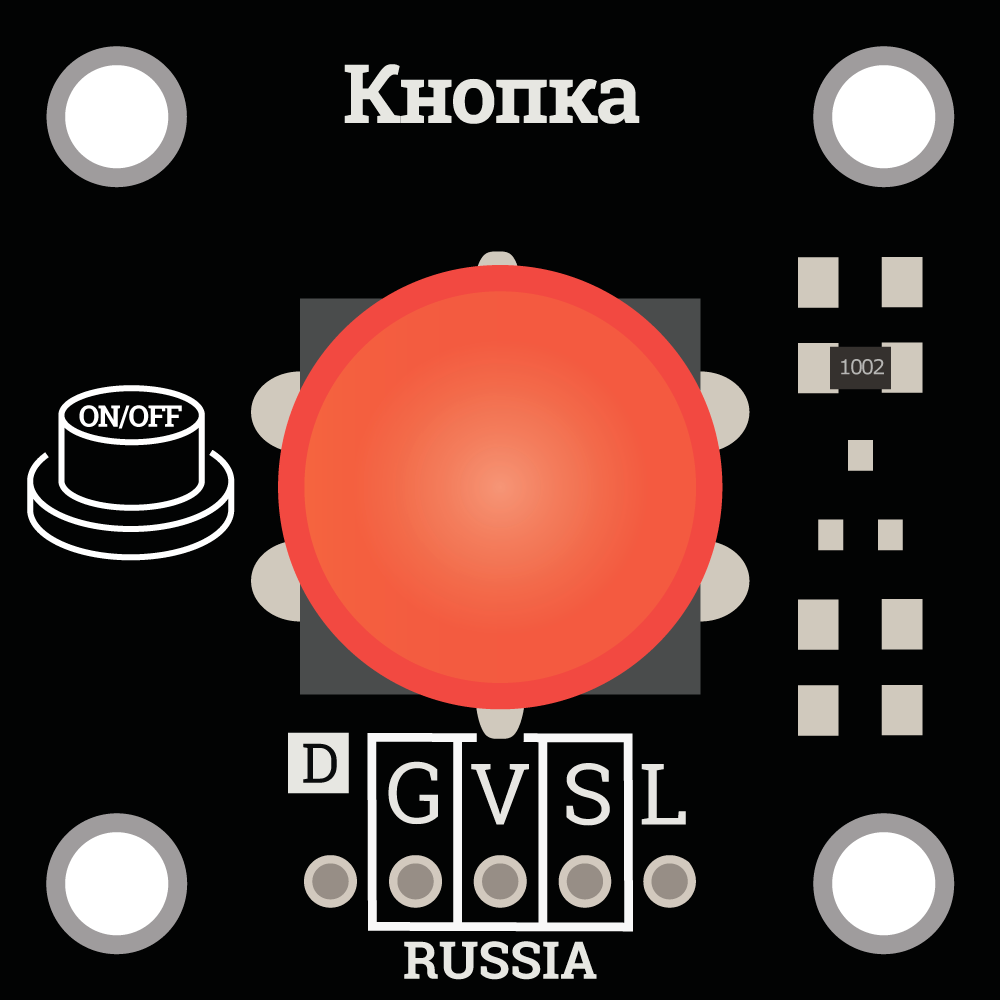
The Button Module Red (Manufacturer: Trema, Part ID: 1) is a push-button switch designed for use in electronic circuits. It features a red button for easy identification and is commonly used to trigger actions or events in various projects. This module is simple to integrate into circuits and is ideal for applications requiring user input, such as controlling devices, starting processes, or navigating menus.
Explore Projects Built with Button Module Red

Explore Projects Built with Button Module Red
Common Applications
- User input for microcontroller-based projects (e.g., Arduino, Raspberry Pi)
- Triggering events in robotics and automation systems
- Reset or power control in electronic devices
- Interactive projects such as games or educational kits
Technical Specifications
The Button Module Red is designed for ease of use and compatibility with a wide range of electronic systems. Below are its key technical details:
Key Specifications
| Parameter | Value |
|---|---|
| Operating Voltage | 3.3V to 5V |
| Maximum Current | 50mA |
| Button Type | Momentary (push-to-make) |
| Dimensions | 20mm x 15mm x 10mm |
| Mounting Type | PCB or breadboard compatible |
| Color | Red |
Pin Configuration
The Button Module Red has a simple 3-pin interface. The table below describes each pin:
| Pin Name | Description |
|---|---|
| GND | Ground connection |
| VCC | Power supply (3.3V to 5V) |
| OUT | Output signal (HIGH when pressed, LOW otherwise) |
Usage Instructions
The Button Module Red is straightforward to use in electronic circuits. Follow the steps below to integrate it into your project:
Connecting the Button Module
- Power the Module: Connect the
VCCpin to a 3.3V or 5V power source and theGNDpin to the ground of your circuit. - Read the Output: Connect the
OUTpin to a digital input pin on your microcontroller or other logic circuit. When the button is pressed, theOUTpin will output a HIGH signal; otherwise, it will remain LOW.
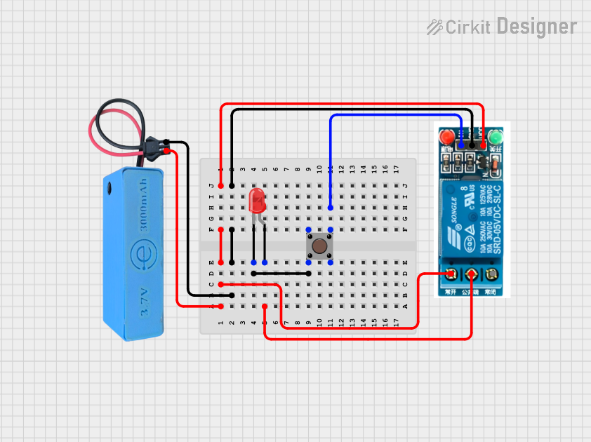
Example Circuit with Arduino UNO
Below is an example of how to connect and use the Button Module Red with an Arduino UNO:
Circuit Diagram
- Connect the
VCCpin of the button module to the 5V pin on the Arduino. - Connect the
GNDpin of the button module to the GND pin on the Arduino. - Connect the
OUTpin of the button module to digital pin 2 on the Arduino.
Example Code
// Example code for using the Button Module Red with Arduino UNO
// This code reads the button state and turns on an LED when the button is pressed.

const int buttonPin = 2;  // Pin connected to the OUT pin of the button module
const int ledPin = 13;    // Pin connected to the built-in LED on the Arduino

void setup() {
  pinMode(buttonPin, INPUT);  // Set the button pin as input
  pinMode(ledPin, OUTPUT);   // Set the LED pin as output
  Serial.begin(9600);        // Initialize serial communication for debugging
}

void loop() {
  int buttonState = digitalRead(buttonPin);  // Read the button state

  if (buttonState == HIGH) {
    // If the button is pressed, turn on the LED
    digitalWrite(ledPin, HIGH);
    Serial.println("Button Pressed!");  // Print message to serial monitor
  } else {
    // If the button is not pressed, turn off the LED
    digitalWrite(ledPin, LOW);
  }

  delay(10);  // Small delay to debounce the button
}
Best Practices
- Use a pull-down resistor (10kΩ) on the
OUTpin if the module does not have an internal pull-down resistor. This ensures the output remains LOW when the button is not pressed. - Avoid exceeding the maximum current rating (50mA) to prevent damage to the module.
- Debounce the button in software or hardware to avoid false triggers caused by mechanical noise.
Troubleshooting and FAQs
Common Issues and Solutions
The button does not respond when pressed.
- Ensure the
VCCandGNDpins are correctly connected to the power supply. - Verify that the
OUTpin is properly connected to the microcontroller or circuit input. - Check for loose connections or damaged wires.
- Ensure the
The output signal is unstable or fluctuates.
- Add a pull-down resistor (10kΩ) to the
OUTpin if not already present. - Implement software debouncing in your code to filter out mechanical noise.
- Add a pull-down resistor (10kΩ) to the
The button works intermittently.
- Inspect the button for physical damage or dirt that may obstruct proper contact.
- Ensure the power supply voltage is stable and within the specified range (3.3V to 5V).
FAQs
Q: Can I use the Button Module Red with a 3.3V microcontroller?
A: Yes, the module is compatible with both 3.3V and 5V systems.
Q: Does the module include an internal pull-down resistor?
A: Some versions of the module may include an internal pull-down resistor. If the output signal is unstable, add an external 10kΩ pull-down resistor.
Q: Can I use this module to control high-power devices?
A: No, the Button Module Red is designed for low-power signal control. Use a relay or transistor circuit to control high-power devices.
By following this documentation, you can effectively integrate the Button Module Red into your projects and troubleshoot any issues that arise.