How to Use contactor: Examples, Pinouts, and Specs
Introduction
A contactor is an electrically controlled switch manufactured by TE, designed for switching electrical power circuits. Unlike standard relays, contactors are specifically engineered to handle higher currents, making them ideal for industrial and commercial applications. They are commonly used in motor control systems, lighting circuits, heating systems, and other high-power electrical devices.
Explore Projects Built with contactor


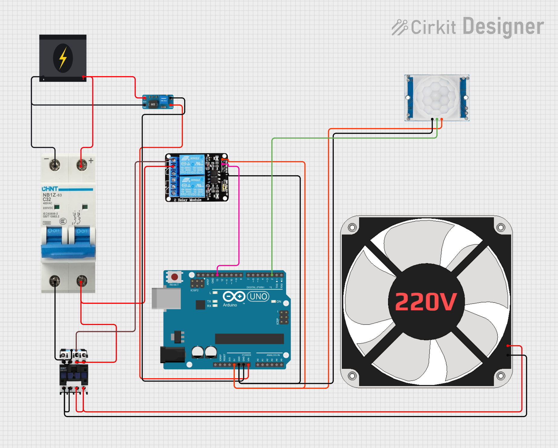
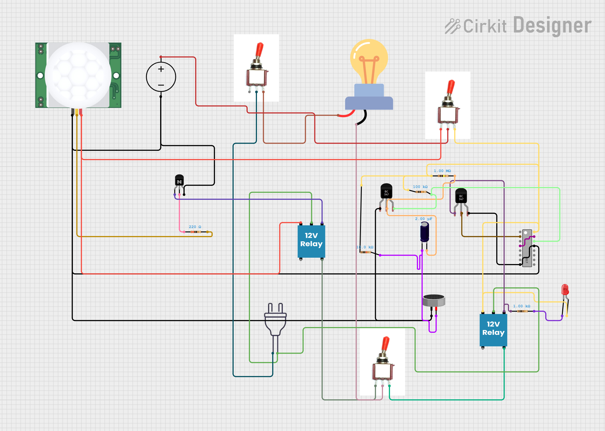
Explore Projects Built with contactor
Common Applications and Use Cases
- Motor starters for industrial machinery
- HVAC systems for controlling compressors and fans
- Lighting control in commercial buildings
- Electric heating systems
- Renewable energy systems, such as solar inverters
- Power distribution and automation systems
Technical Specifications
Below are the general technical specifications for a TE-manufactured contactor. Always refer to the specific datasheet for the exact model you are using.
Key Technical Details
- Rated Voltage: 24V DC or 230V AC (depending on model)
- Rated Current: Up to 100A (varies by model)
- Coil Voltage: 12V, 24V, or 230V (model-dependent)
- Contact Configuration: SPST, SPDT, DPST, or DPDT
- Mechanical Life: Up to 10 million operations
- Electrical Life: Up to 1 million operations (at rated load)
- Operating Temperature Range: -25°C to +70°C
- Insulation Resistance: >100 MΩ at 500V DC
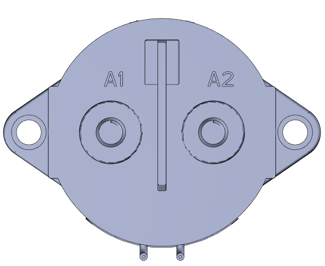
Pin Configuration and Descriptions
The pin configuration of a contactor depends on its specific design. Below is a general example for a DPST (Double Pole Single Throw) contactor:
| Pin Number | Name | Description |
|---|---|---|
| 1 | Coil Terminal A | One side of the electromagnetic coil. Connect to the control voltage source. |
| 2 | Coil Terminal B | The other side of the electromagnetic coil. Connect to the control voltage source. |
| 3 | Load Terminal 1 | First input terminal for the high-power circuit. |
| 4 | Load Terminal 2 | First output terminal for the high-power circuit. |
| 5 | Load Terminal 3 | Second input terminal for the high-power circuit. |
| 6 | Load Terminal 4 | Second output terminal for the high-power circuit. |
Note: The exact pin configuration may vary depending on the contactor model. Always consult the datasheet for your specific component.
Usage Instructions
How to Use the Contactor in a Circuit
- Power the Coil: Connect the coil terminals (e.g., pins 1 and 2) to the appropriate control voltage. Ensure the voltage matches the coil rating (e.g., 24V DC or 230V AC).
- Connect the Load: Wire the high-power circuit to the load terminals (e.g., pins 3, 4, 5, and 6). Ensure the load current does not exceed the contactor's rated current.
- Control the Circuit: Use a low-power control signal (e.g., from a microcontroller or switch) to energize the coil. When the coil is energized, the contactor closes the high-power circuit, allowing current to flow.
Important Considerations and Best Practices
- Voltage Matching: Always ensure the control voltage matches the coil voltage rating.
- Current Rating: Verify that the load current does not exceed the contactor's rated current.
- Snubber Circuit: For AC loads, consider adding a snubber circuit across the contacts to reduce arcing and prolong contact life.
- Mounting: Securely mount the contactor to prevent vibration or movement during operation.
- Safety: Always disconnect power before wiring or servicing the contactor.
Example: Using a Contactor with an Arduino UNO
Below is an example of how to control a 24V DC contactor using an Arduino UNO and a transistor as a driver.
// Define the pin connected to the transistor base
const int controlPin = 9;

void setup() {
  pinMode(controlPin, OUTPUT); // Set the control pin as an output
}

void loop() {
  digitalWrite(controlPin, HIGH); // Energize the contactor coil
  delay(5000); // Keep the contactor closed for 5 seconds

  digitalWrite(controlPin, LOW); // De-energize the contactor coil
  delay(5000); // Keep the contactor open for 5 seconds
}
Circuit Notes:
- Use a suitable NPN transistor (e.g., 2N2222) to drive the contactor coil.
- Place a flyback diode (e.g., 1N4007) across the coil terminals to protect the transistor from voltage spikes.
- Connect the Arduino control pin to the transistor base through a 1kΩ resistor.
Troubleshooting and FAQs
Common Issues and Solutions
Contactor Does Not Activate:
- Cause: Insufficient control voltage or incorrect wiring.
- Solution: Verify the control voltage matches the coil rating and check the wiring.
Excessive Arcing at Contacts:
- Cause: High inrush current or inductive load.
- Solution: Add a snubber circuit or use a contactor rated for inductive loads.
Overheating:
- Cause: Load current exceeds the contactor's rated current.
- Solution: Reduce the load current or use a higher-rated contactor.
Buzzing Noise:
- Cause: Loose coil connections or incorrect AC frequency.
- Solution: Tighten connections and ensure the control voltage frequency matches the contactor's specification.
FAQs
Q: Can I use a contactor for DC loads?
A: Yes, but ensure the contactor is rated for DC operation. DC contactors are designed to handle the challenges of breaking DC circuits, such as higher arcing.
Q: How do I choose the right contactor for my application?
A: Consider the load type (AC or DC), voltage, current, and whether the load is resistive or inductive. Select a contactor with appropriate ratings and features.
Q: Can I control a contactor directly with an Arduino?
A: No, the Arduino cannot supply enough current to energize the coil. Use a transistor or relay as an intermediary driver.
Q: What is the difference between a relay and a contactor?
A: Relays are designed for low-power applications, while contactors are built to handle high-power circuits and higher currents.
By following this documentation, you can effectively integrate a TE contactor into your electrical or automation projects.