Cirkit Designer Logo
Cirkit Designer
Your all-in-one circuit design IDE
Home / 
Component Documentation

How to Use PmodALS: Examples, Pinouts, and Specs

Image of PmodALS
Cirkit Designer LogoDesign with PmodALS in Cirkit Designer

Introduction

The PmodALS, manufactured by Digilent, is a compact ambient light sensor module designed to measure light intensity. It utilizes a photodiode and associated circuitry to convert ambient light levels into an analog voltage signal. This module is ideal for applications requiring light detection, such as automatic lighting systems, display brightness adjustment, and environmental monitoring.

The PmodALS is easy to integrate with microcontrollers and other digital devices, making it a versatile choice for both hobbyists and professionals.

Explore Projects Built with PmodALS

Use Cirkit Designer to design, explore, and prototype these projects online. Some projects support real-time simulation. Click "Open Project" to start designing instantly!
ESP32-Controlled AC Lighting System with Power Monitoring
Image of Smart Energy Meter: A project utilizing PmodALS in a practical application
This circuit features an ESP32 microcontroller interfaced with a PZEM004T power monitoring module and a 4-channel relay module controlling multiple AC LED bulbs. The ESP32 uses GPIO pins to control the relays, which in turn switch the LED bulbs on and off. The PZEM004T is connected to the ESP32 for communication and to a current sensor for monitoring power consumption of the connected load through the relay contacts.
Cirkit Designer LogoOpen Project in Cirkit Designer
ESP32 and PZEM004T-Based Smart Light Control with Current Sensing
Image of Smart Energy Meter: A project utilizing PmodALS in a practical application
This circuit is designed for monitoring and controlling AC loads using an ESP32 microcontroller. It includes a PZEM004T module for measuring voltage, current, and power, and a 4-channel relay module to switch three LED bulbs. The ESP32 communicates with the PZEM004T via UART and controls the relays to manage the connected loads.
Cirkit Designer LogoOpen Project in Cirkit Designer
ESP32-Based Smart Environmental Monitoring System with Relay Control
Image of SOCOTECO: A project utilizing PmodALS in a practical application
This is a smart environmental monitoring and control system featuring an ESP32 microcontroller interfaced with a PZEM004T for power monitoring, relay modules for actuating bulbs and a fan, and an LCD for user interface. It includes flame, gas, and vibration sensors for safety monitoring purposes.
Cirkit Designer LogoOpen Project in Cirkit Designer
PLC-Controlled Power Window System with Infrared Sensing and Relay Module
Image of wiring FYP: A project utilizing PmodALS in a practical application
This circuit is designed to control a motorized window system using a PLC (Programmable Logic Controller) and an array of sensors and switches. It includes power supplies for 12V and 24V DC, an MCB (Miniature Circuit Breaker) for protection, and a relay module interfaced with an Arduino for additional control logic. The PLC manages inputs from pushbuttons, a 3-position switch, infrared proximity sensors, and an emergency stop, and it controls outputs such as the motor speed controller, lamps, and solenoid valves.
Cirkit Designer LogoOpen Project in Cirkit Designer

Explore Projects Built with PmodALS

Use Cirkit Designer to design, explore, and prototype these projects online. Some projects support real-time simulation. Click "Open Project" to start designing instantly!
Image of Smart Energy Meter: A project utilizing PmodALS in a practical application
ESP32-Controlled AC Lighting System with Power Monitoring
This circuit features an ESP32 microcontroller interfaced with a PZEM004T power monitoring module and a 4-channel relay module controlling multiple AC LED bulbs. The ESP32 uses GPIO pins to control the relays, which in turn switch the LED bulbs on and off. The PZEM004T is connected to the ESP32 for communication and to a current sensor for monitoring power consumption of the connected load through the relay contacts.
Cirkit Designer LogoOpen Project in Cirkit Designer
Image of Smart Energy Meter: A project utilizing PmodALS in a practical application
ESP32 and PZEM004T-Based Smart Light Control with Current Sensing
This circuit is designed for monitoring and controlling AC loads using an ESP32 microcontroller. It includes a PZEM004T module for measuring voltage, current, and power, and a 4-channel relay module to switch three LED bulbs. The ESP32 communicates with the PZEM004T via UART and controls the relays to manage the connected loads.
Cirkit Designer LogoOpen Project in Cirkit Designer
Image of SOCOTECO: A project utilizing PmodALS in a practical application
ESP32-Based Smart Environmental Monitoring System with Relay Control
This is a smart environmental monitoring and control system featuring an ESP32 microcontroller interfaced with a PZEM004T for power monitoring, relay modules for actuating bulbs and a fan, and an LCD for user interface. It includes flame, gas, and vibration sensors for safety monitoring purposes.
Cirkit Designer LogoOpen Project in Cirkit Designer
Image of wiring FYP: A project utilizing PmodALS in a practical application
PLC-Controlled Power Window System with Infrared Sensing and Relay Module
This circuit is designed to control a motorized window system using a PLC (Programmable Logic Controller) and an array of sensors and switches. It includes power supplies for 12V and 24V DC, an MCB (Miniature Circuit Breaker) for protection, and a relay module interfaced with an Arduino for additional control logic. The PLC manages inputs from pushbuttons, a 3-position switch, infrared proximity sensors, and an emergency stop, and it controls outputs such as the motor speed controller, lamps, and solenoid valves.
Cirkit Designer LogoOpen Project in Cirkit Designer

Technical Specifications

The following are the key technical details of the PmodALS:

  • Operating Voltage: 3.3V
  • Output Voltage Range: 0V to 3.3V (proportional to light intensity)
  • Interface: Analog output
  • Light Sensitivity: Up to 1000 lux
  • Power Consumption: Low power operation
  • Dimensions: Compact form factor (0.8" × 0.8")

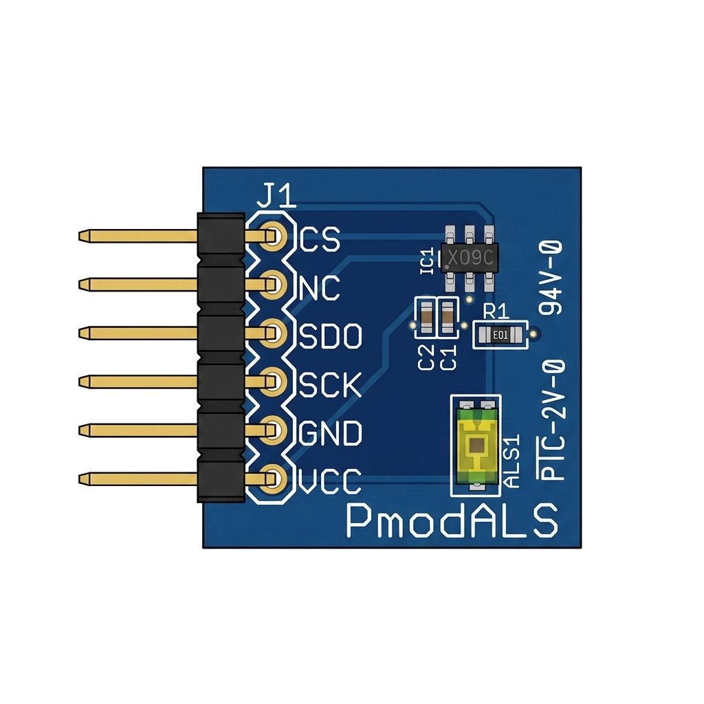
Pin Configuration and Descriptions

The PmodALS uses a 6-pin connector. The pin configuration is as follows:

Pin Number Pin Name Description
1 VCC Power supply input (3.3V)
2 GND Ground
3 OUT Analog output signal (light intensity)
4 NC Not connected
5 NC Not connected
6 NC Not connected

Usage Instructions

How to Use the PmodALS in a Circuit

  1. Power the Module: Connect the VCC pin to a 3.3V power source and the GND pin to ground.
  2. Read the Output: Connect the OUT pin to an analog input pin on your microcontroller or ADC (Analog-to-Digital Converter). The voltage on the OUT pin will vary proportionally with the ambient light intensity.
  3. Process the Signal: Use your microcontroller to read the analog voltage and convert it into a meaningful light intensity value.

Important Considerations and Best Practices

  • Voltage Compatibility: Ensure that your microcontroller operates at 3.3V logic levels to avoid damaging the PmodALS.
  • Placement: Place the PmodALS in an area where it can accurately measure ambient light without obstructions or interference.
  • Calibration: Depending on your application, you may need to calibrate the sensor to map the output voltage to specific light intensity values (e.g., lux).

Example: Connecting PmodALS to an Arduino UNO

Although the Arduino UNO operates at 5V logic, you can use a voltage divider or level shifter to safely interface with the PmodALS. Below is an example code snippet for reading the sensor's output:

// Define the analog pin connected to the PmodALS OUT pin
const int sensorPin = A0;

void setup() {
  // Initialize serial communication for debugging
  Serial.begin(9600);
}

void loop() {
  // Read the analog value from the sensor
  int sensorValue = analogRead(sensorPin);

  // Convert the analog value to voltage (assuming 3.3V reference)
  float voltage = sensorValue * (3.3 / 1023.0);

  // Print the voltage to the serial monitor
  Serial.print("Ambient Light Voltage: ");
  Serial.print(voltage);
  Serial.println(" V");

  // Add a small delay for stability
  delay(500);
}

Note: If using a 5V Arduino, ensure the OUT pin voltage does not exceed the ADC input range by using a voltage divider.

Troubleshooting and FAQs

Common Issues

  1. No Output Signal:

    • Cause: Incorrect wiring or insufficient power supply.
    • Solution: Double-check the connections and ensure the module is powered with 3.3V.
  2. Inconsistent Readings:

    • Cause: Electrical noise or unstable power supply.
    • Solution: Use decoupling capacitors near the power pins to stabilize the supply voltage.
  3. Output Voltage Stuck at Maximum or Minimum:

    • Cause: Sensor saturation or insufficient ambient light.
    • Solution: Adjust the sensor's placement to ensure it is exposed to appropriate light levels.

FAQs

Q: Can the PmodALS be used with a 5V microcontroller?
A: Yes, but you must use a voltage divider or level shifter to ensure the OUT pin voltage does not exceed the microcontroller's ADC input range.

Q: How do I convert the output voltage to lux?
A: The PmodALS output voltage is proportional to light intensity. Refer to the module's datasheet for the exact conversion formula or perform a calibration using a known light source.

Q: Can the PmodALS detect infrared light?
A: No, the PmodALS is designed to detect visible light and is not sensitive to infrared wavelengths.

By following this documentation, you can effectively integrate the PmodALS into your projects and troubleshoot any issues that arise.