How to Use LED Red Light Strobe: Examples, Pinouts, and Specs

Introduction
The LED Red Light Strobe is a light-emitting diode (LED) designed to emit a bright red light in a flashing strobe pattern. This component is widely used in applications requiring attention-grabbing visual effects, such as signaling, decoration, emergency lighting, and stage lighting. Its compact size, low power consumption, and long lifespan make it a versatile and reliable choice for various projects.
Common applications include:
- Emergency signaling devices
- Decorative lighting for events or displays
- Visual effects in stage or theatrical productions
- Warning indicators in industrial or automotive systems
Explore Projects Built with LED Red Light Strobe
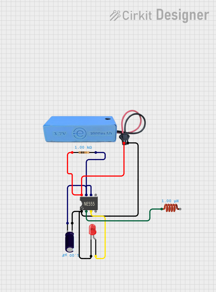
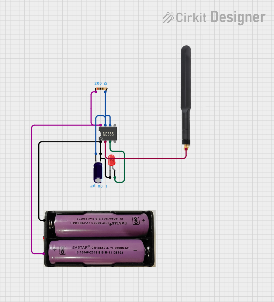
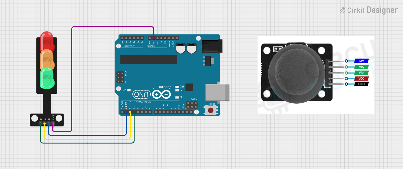
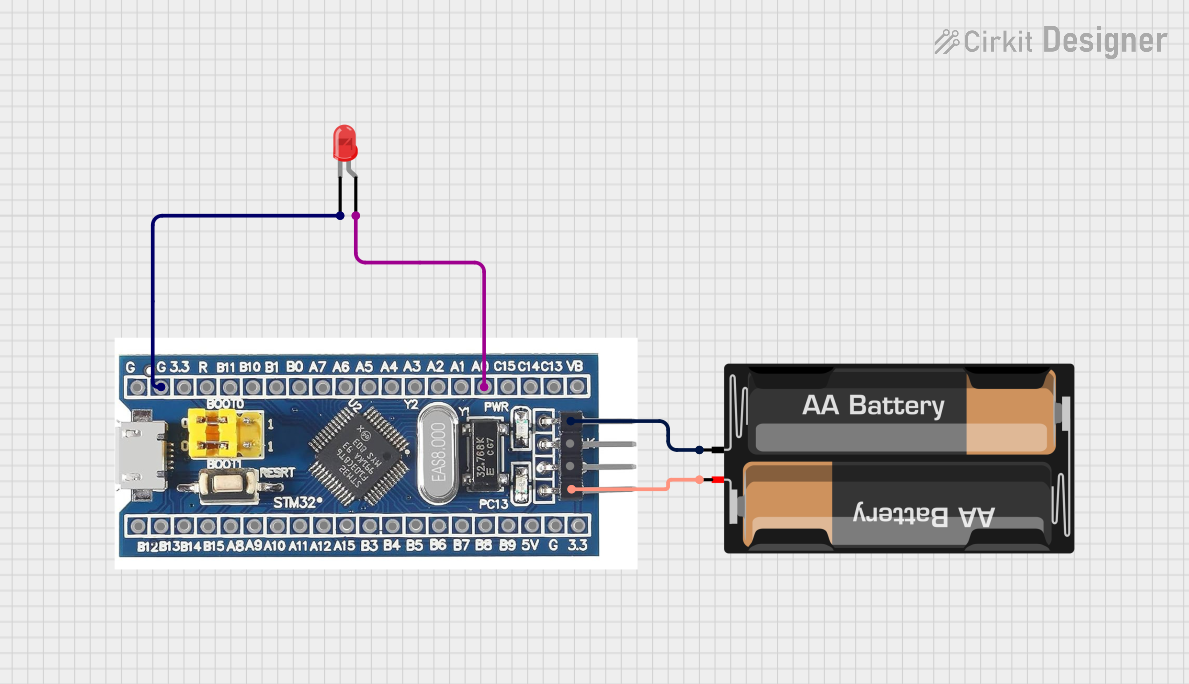
Explore Projects Built with LED Red Light Strobe
Technical Specifications
The following table outlines the key technical details of the LED Red Light Strobe:
| Parameter | Value |
|---|---|
| Operating Voltage | 3V to 12V |
| Operating Current | 20mA to 30mA |
| Flash Frequency | 1Hz to 3Hz (adjustable) |
| Light Color | Red |
| Viewing Angle | 30° to 60° |
| Power Consumption | < 0.5W |
| Lifespan | 50,000 hours (typical) |
| Dimensions | 5mm or 10mm (common sizes) |
Pin Configuration and Descriptions
The LED Red Light Strobe typically has two pins, as described below:
| Pin | Name | Description |
|---|---|---|
| 1 | Anode (+) | Connect to the positive terminal of the power supply. |
| 2 | Cathode (-) | Connect to the negative terminal or ground. |
Usage Instructions
How to Use the Component in a Circuit
- Power Supply: Ensure the power supply voltage matches the operating voltage range of the LED Red Light Strobe (3V to 12V). Use a current-limiting resistor to prevent overcurrent damage.
- Connection:
- Connect the anode (+) pin to the positive terminal of the power supply.
- Connect the cathode (-) pin to the ground or negative terminal.
- Resistor Selection: Calculate the resistor value using Ohm's Law: [ R = \frac{V_{supply} - V_{forward}}{I_{forward}} ] Where (V_{supply}) is the supply voltage, (V_{forward}) is the forward voltage of the LED (typically 2V for red LEDs), and (I_{forward}) is the forward current (e.g., 20mA).
- Optional Adjustments: If the LED has an adjustable flash frequency, use the built-in potentiometer or external control circuit to set the desired strobe rate.
Example: Connecting to an Arduino UNO
The LED Red Light Strobe can be controlled using an Arduino UNO to create custom flashing patterns. Below is an example code:
// Example code to control an LED Red Light Strobe with Arduino UNO
// Connect the anode (+) of the LED to pin 9 via a 220-ohm resistor
// Connect the cathode (-) to the ground (GND) pin of the Arduino

const int ledPin = 9; // Pin connected to the LED

void setup() {
  pinMode(ledPin, OUTPUT); // Set the LED pin as an output
}

void loop() {
  digitalWrite(ledPin, HIGH); // Turn the LED on
  delay(500);                // Wait for 500ms (adjust for strobe speed)
  digitalWrite(ledPin, LOW);  // Turn the LED off
  delay(500);                // Wait for 500ms (adjust for strobe speed)
}
Important Considerations and Best Practices
- Current Limiting: Always use a resistor to limit the current through the LED and prevent damage.
- Polarity: Ensure correct polarity when connecting the LED. Reversing the connections may damage the component.
- Heat Dissipation: While LEDs generate minimal heat, ensure proper ventilation if used in enclosed spaces.
- Voltage Range: Do not exceed the maximum operating voltage to avoid permanent damage.
Troubleshooting and FAQs
Common Issues and Solutions
LED Does Not Light Up:
- Check the polarity of the connections (anode and cathode).
- Verify the power supply voltage and ensure it is within the operating range.
- Ensure the current-limiting resistor is correctly calculated and connected.
LED Flickers or Blinks Irregularly:
- Check for loose or poor connections in the circuit.
- Ensure the power supply is stable and not fluctuating.
LED Burns Out Quickly:
- Verify that the current-limiting resistor is properly sized to limit the current to the recommended range.
- Ensure the supply voltage does not exceed the maximum rating.
Strobe Frequency Cannot Be Adjusted:
- If the LED has an adjustable frequency feature, check the potentiometer or control circuit for proper operation.
- Ensure the external control circuit (if used) is functioning correctly.
FAQs
Q: Can I use the LED Red Light Strobe with a 5V USB power supply?
A: Yes, you can use a 5V USB power supply. Ensure you include a suitable current-limiting resistor to protect the LED.
Q: How do I increase the brightness of the LED?
A: The brightness is determined by the current flowing through the LED. However, do not exceed the maximum forward current (typically 20mA to 30mA) to avoid damage.
Q: Can I use this LED outdoors?
A: The LED itself is not weatherproof. If outdoor use is required, ensure it is enclosed in a waterproof housing.
Q: What happens if I connect the LED without a resistor?
A: Without a resistor, the LED may draw excessive current, leading to overheating and permanent damage.
By following this documentation, you can effectively integrate the LED Red Light Strobe into your projects and troubleshoot common issues with ease.