Cirkit Designer
Your all-in-one circuit design IDE
Home /
Component Documentation
How to Use Tanauan City College: Examples, Pinouts, and Specs

Introduction
- A relay is an electromechanical switch used to control a high-power circuit with a low-power signal. It is widely used in applications where electrical isolation is required between the control circuit and the load circuit.
- Common applications include home automation, motor control, industrial equipment, and automotive systems. Relays are also frequently used in Arduino and microcontroller-based projects to control devices like lights, fans, and other appliances.
Explore Projects Built with Tanauan City College
Load Cell Signal Conditioning Circuit with Dual Op-Amp and PNP Transistor

This analog circuit is designed for signal conditioning of a load cell output using a PNP transistor and a dual operational amplifier (TLC272CP). It includes resistors for biasing and current limiting, and tantalum capacitors for filtering or timing, with a multimeter connected for monitoring voltage and ground connections.
Arduino UNO-Based Water Quality Monitoring System with GSM and Solar Power
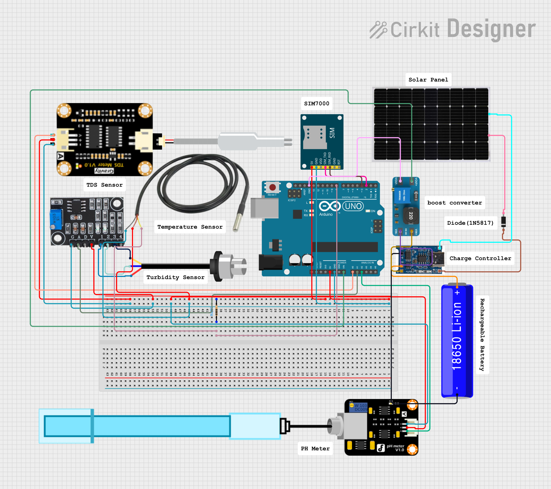
This circuit is a water quality monitoring system powered by a solar panel and a Li-ion battery, featuring an Arduino UNO that collects data from various sensors including TDS, turbidity, pH, and temperature. The collected data is transmitted via a SIM800L GSM module, allowing remote monitoring of water quality parameters.
Arduino UNO Bluetooth-Controlled Servo with LDR Feedback
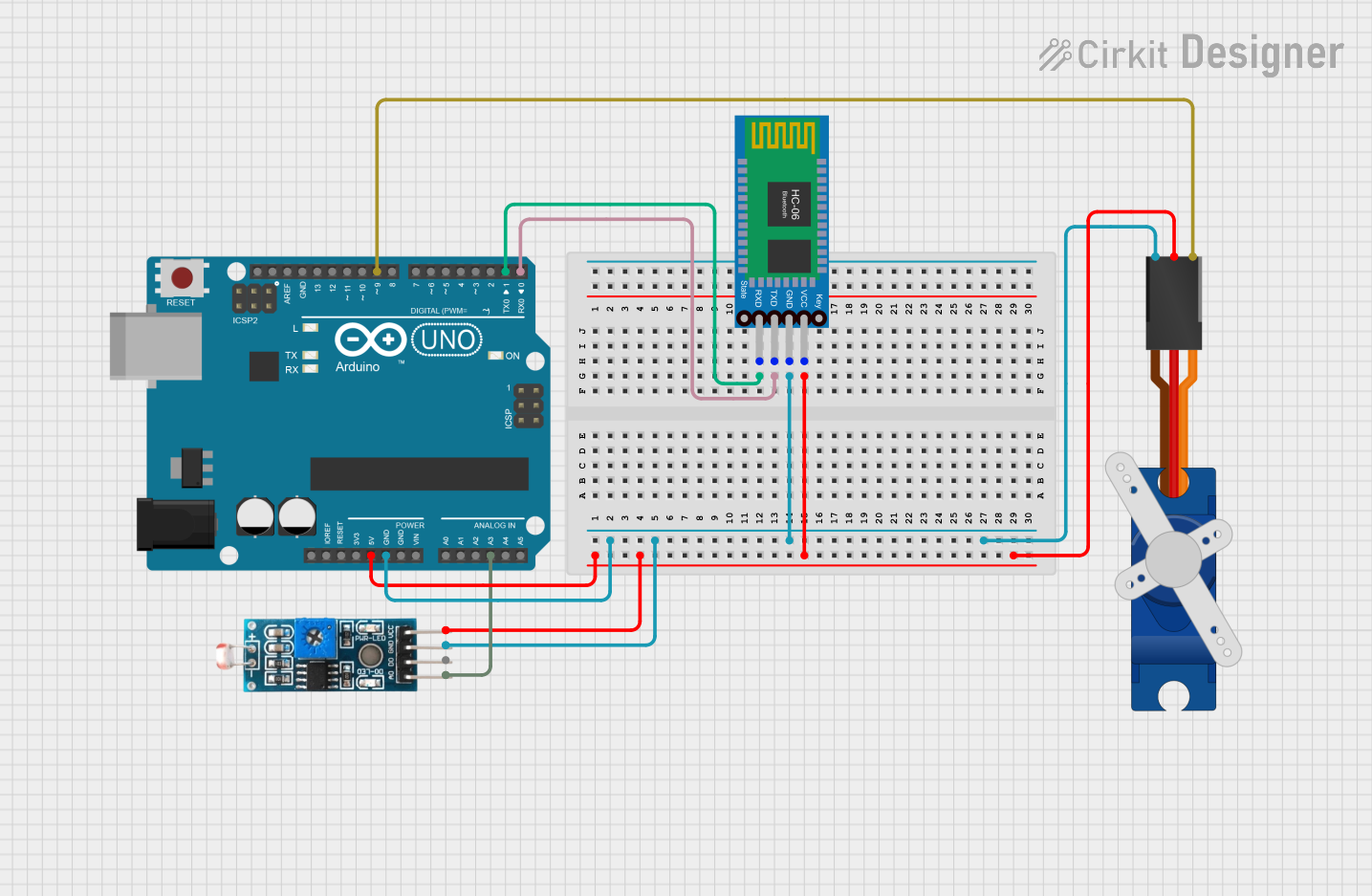
This circuit features an Arduino UNO microcontroller interfaced with a Bluetooth HC-06 module for wireless communication, a Tower Pro SG90 servo motor for actuation, and a Module LDR for light intensity sensing. The Arduino controls the servo based on the data received from the LDR or Bluetooth module. The Bluetooth module enables remote control or data exchange, while the LDR provides environmental feedback to the Arduino.
Arduino-Controlled Servo with Light Sensing
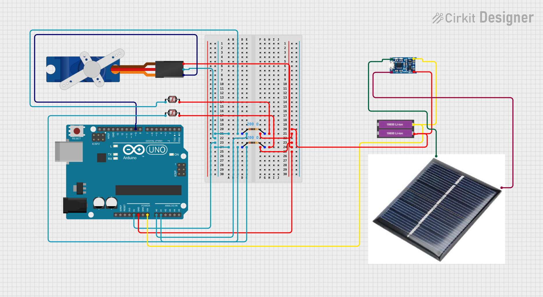
This circuit features an Arduino UNO microcontroller interfaced with two photocells (LDRs) and a servo motor. The photocells are connected to analog inputs A0 and A1, and their average light intensity reading is used to control the position of the servo motor connected to digital pin D9. The circuit is powered by a pair of 18650 Li-ion batteries, which are also connected to a TP4056 charging module that can be charged via a solar cell, providing a renewable energy source for the system.
Explore Projects Built with Tanauan City College
Load Cell Signal Conditioning Circuit with Dual Op-Amp and PNP Transistor
This analog circuit is designed for signal conditioning of a load cell output using a PNP transistor and a dual operational amplifier (TLC272CP). It includes resistors for biasing and current limiting, and tantalum capacitors for filtering or timing, with a multimeter connected for monitoring voltage and ground connections.
Arduino UNO-Based Water Quality Monitoring System with GSM and Solar Power
This circuit is a water quality monitoring system powered by a solar panel and a Li-ion battery, featuring an Arduino UNO that collects data from various sensors including TDS, turbidity, pH, and temperature. The collected data is transmitted via a SIM800L GSM module, allowing remote monitoring of water quality parameters.
Arduino UNO Bluetooth-Controlled Servo with LDR Feedback
This circuit features an Arduino UNO microcontroller interfaced with a Bluetooth HC-06 module for wireless communication, a Tower Pro SG90 servo motor for actuation, and a Module LDR for light intensity sensing. The Arduino controls the servo based on the data received from the LDR or Bluetooth module. The Bluetooth module enables remote control or data exchange, while the LDR provides environmental feedback to the Arduino.
Arduino-Controlled Servo with Light Sensing
This circuit features an Arduino UNO microcontroller interfaced with two photocells (LDRs) and a servo motor. The photocells are connected to analog inputs A0 and A1, and their average light intensity reading is used to control the position of the servo motor connected to digital pin D9. The circuit is powered by a pair of 18650 Li-ion batteries, which are also connected to a TP4056 charging module that can be charged via a solar cell, providing a renewable energy source for the system.
Technical Specifications
- Component Name: Relay
- Manufacturer: N/A
- Part ID: RELAY
- Description: A relay is a switch that opens and closes circuits electromechanically or electronically. It allows a low-power signal to control a high-power circuit.
Key Technical Details
| Parameter | Value/Range |
|---|---|
| Operating Voltage | 5V, 12V, or 24V (depending on model) |
| Coil Resistance | Typically 70Ω to 400Ω |
| Switching Voltage | Up to 250V AC or 30V DC |
| Switching Current | Up to 10A |
| Contact Configuration | SPDT (Single Pole Double Throw) or DPDT (Double Pole Double Throw) |
| Isolation | Electrical isolation between control and load circuits |
Pin Configuration
| Pin Number | Pin Name | Description |
|---|---|---|
| 1 | Coil+ (VCC) | Positive terminal of the relay coil |
| 2 | Coil- (GND) | Negative terminal of the relay coil |
| 3 | Common (COM) | Common terminal for the load circuit |
| 4 | Normally Open (NO) | Open circuit when the relay is inactive; closes when activated |
| 5 | Normally Closed (NC) | Closed circuit when the relay is inactive; opens when activated |
Usage Instructions
Connecting the Relay to a Circuit:
- Connect the relay's coil terminals (Coil+ and Coil-) to the control circuit. Ensure the voltage matches the relay's operating voltage (e.g., 5V, 12V).
- Connect the load circuit to the Common (COM) terminal and either the Normally Open (NO) or Normally Closed (NC) terminal, depending on the desired behavior.
Important Considerations:
- Always check the relay's voltage and current ratings to ensure compatibility with your circuit.
- Use a flyback diode across the relay coil to protect the control circuit from voltage spikes when the relay is deactivated.
- Ensure proper electrical isolation between the control and load circuits to prevent damage to sensitive components.
Using a Relay with Arduino UNO: Below is an example of how to control a relay using an Arduino UNO:
// Example: Controlling a relay with Arduino UNO const int relayPin = 7; // Pin connected to the relay module void setup() { pinMode(relayPin, OUTPUT); // Set the relay pin as an output digitalWrite(relayPin, LOW); // Ensure the relay is off initially } void loop() { digitalWrite(relayPin, HIGH); // Turn the relay on delay(1000); // Keep it on for 1 second digitalWrite(relayPin, LOW); // Turn the relay off delay(1000); // Keep it off for 1 second }- Note: Use a relay module with built-in driver circuitry when connecting directly to an Arduino. This ensures the Arduino can safely drive the relay.
Troubleshooting and FAQs
Common Issues
Relay not activating:
- Cause: Insufficient voltage or current to the relay coil.
- Solution: Verify the control circuit's voltage and current match the relay's specifications.
Load not switching:
- Cause: Incorrect wiring of the load circuit.
- Solution: Double-check the connections to the Common (COM), Normally Open (NO), and Normally Closed (NC) terminals.
Arduino resets when activating the relay:
- Cause: Voltage spikes from the relay coil affecting the Arduino.
- Solution: Add a flyback diode across the relay coil and ensure proper power supply decoupling.
Relay makes a buzzing sound:
- Cause: Insufficient or unstable voltage to the relay coil.
- Solution: Use a stable power supply and ensure the control circuit provides the required voltage.
FAQs
Q: Can I use a relay to control an AC appliance?
- A: Yes, as long as the relay's switching voltage and current ratings are compatible with the appliance.
Q: Do I need a separate power supply for the relay?
- A: It depends on the relay's operating voltage. If the control circuit cannot provide sufficient current, a separate power supply may be required.
Q: What is the purpose of the flyback diode?
- A: The flyback diode protects the control circuit from voltage spikes generated when the relay coil is de-energized.
Q: Can I use a relay to switch both AC and DC loads?
- A: Yes, but ensure the relay's specifications support the voltage and current requirements of the load.