How to Use Signal Tower with buzzer: Examples, Pinouts, and Specs
Introduction
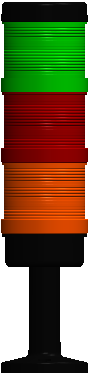
The Signal Tower with Buzzer is a versatile visual and audible alerting device that combines a tower light and a buzzer. It is widely used in industrial and commercial settings to indicate machine status, process alarms, or other operational conditions. The device typically features multiple colored LED lights (e.g., red, yellow, green) and a built-in buzzer to provide clear and immediate status feedback.
Explore Projects Built with Signal Tower with buzzer

Explore Projects Built with Signal Tower with buzzer
Common Applications and Use Cases
- Industrial Automation: Indicating machine status (e.g., running, idle, fault).
- Safety Systems: Alerting operators to hazardous conditions or emergencies.
- Production Lines: Signaling process stages or completion.
- Commercial Settings: Queue management or customer service notifications.
Technical Specifications
Key Technical Details
| Parameter | Value |
|---|---|
| Operating Voltage | 12V DC / 24V DC / 110-240V AC |
| Power Consumption | Typically 2-5W (varies by model) |
| Light Colors | Red, Yellow, Green (optional Blue) |
| Buzzer Sound Level | 70-90 dB at 1 meter |
| Mounting Options | Pole mount, wall mount, or base mount |
| Operating Temperature | -10°C to 50°C |
| Material | Polycarbonate (lens), ABS (housing) |
| IP Rating | IP54 to IP65 (depending on model) |
Pin Configuration and Descriptions
The Signal Tower with Buzzer typically has multiple wires for connection. Below is a common pinout configuration:
| Wire Color | Function |
|---|---|
| Red | Power Supply (+) |
| Black | Power Supply (-) / Ground |
| Green | Green LED Control |
| Yellow | Yellow LED Control |
| Blue | Red LED Control |
| White | Buzzer Control |
Note: The exact wire colors and functions may vary by manufacturer. Always refer to the datasheet for your specific model.
Usage Instructions
How to Use the Component in a Circuit
- Power Supply: Connect the red wire to the positive terminal of the power supply and the black wire to the ground.
- Control Signals: Use switches, relays, or microcontroller GPIO pins to control the green, yellow, blue, and white wires. Applying voltage to these wires activates the corresponding light or buzzer.
- Mounting: Secure the signal tower using the provided mounting hardware. Ensure it is visible and audible in the intended environment.
Important Considerations and Best Practices
- Voltage Compatibility: Verify the operating voltage of the signal tower matches your power supply.
- Current Limiting: Use appropriate resistors or current-limiting devices if required.
- Environmental Protection: Choose a model with an appropriate IP rating for outdoor or dusty environments.
- Microcontroller Integration: When connecting to a microcontroller (e.g., Arduino UNO), use transistors or relays to handle the higher current requirements of the lights and buzzer.
Example: Connecting to an Arduino UNO
Below is an example of how to connect and control a Signal Tower with Buzzer using an Arduino UNO.
Circuit Diagram
- Connect the red wire to the 5V pin on the Arduino.
- Connect the black wire to the GND pin on the Arduino.
- Use digital pins (e.g., D2, D3, D4, D5) to control the green, yellow, blue, and white wires via NPN transistors.
Arduino Code
// Define pin connections for the Signal Tower
const int greenLED = 2;  // Green LED control pin
const int yellowLED = 3; // Yellow LED control pin
const int redLED = 4;    // Red LED control pin
const int buzzer = 5;    // Buzzer control pin

void setup() {
  // Set pins as outputs
  pinMode(greenLED, OUTPUT);
  pinMode(yellowLED, OUTPUT);
  pinMode(redLED, OUTPUT);
  pinMode(buzzer, OUTPUT);
}

void loop() {
  // Example sequence: Green light ON, then Yellow, then Red, with buzzer
  digitalWrite(greenLED, HIGH); // Turn on Green LED
  delay(1000);                  // Wait for 1 second
  digitalWrite(greenLED, LOW);  // Turn off Green LED

  digitalWrite(yellowLED, HIGH); // Turn on Yellow LED
  delay(1000);                   // Wait for 1 second
  digitalWrite(yellowLED, LOW);  // Turn off Yellow LED

  digitalWrite(redLED, HIGH);    // Turn on Red LED
  digitalWrite(buzzer, HIGH);    // Turn on Buzzer
  delay(1000);                   // Wait for 1 second
  digitalWrite(redLED, LOW);     // Turn off Red LED
  digitalWrite(buzzer, LOW);     // Turn off Buzzer
}
Note: Use appropriate transistors or relays if the Signal Tower operates at a voltage higher than 5V.
Troubleshooting and FAQs
Common Issues and Solutions
Lights or Buzzer Not Working:
- Check the power supply voltage and connections.
- Verify that the control signals are being applied correctly.
- Inspect for damaged wires or loose connections.
Buzzer Too Quiet:
- Ensure the buzzer is not obstructed.
- Verify the operating voltage matches the buzzer's specifications.
Intermittent Operation:
- Check for loose connections or unstable power supply.
- Ensure the control signals are not being toggled too quickly.
Microcontroller Cannot Drive the Tower:
- Use transistors or relays to handle the higher current and voltage requirements.
FAQs
Can I use the Signal Tower outdoors?
- Yes, but ensure the model has an appropriate IP rating (e.g., IP65) for outdoor use.
Can I control the Signal Tower with a PLC?
- Yes, the Signal Tower is compatible with PLCs. Use the PLC's output relays or transistors to control the lights and buzzer.
What is the maximum distance for wiring?
- This depends on the wire gauge and voltage drop. For long distances, use thicker wires to minimize voltage loss.
Can I replace the buzzer with a quieter one?
- Some models allow buzzer replacement. Check the manufacturer's documentation for compatibility.
By following this documentation, you can effectively integrate and troubleshoot the Signal Tower with Buzzer in your projects.