How to Use ESP32-Cam Ov5640: Examples, Pinouts, and Specs
Introduction
The ESP32-Cam Ov5640 is a compact and versatile camera module manufactured by diymore (Part ID: AM03DE-FBBA0050-002). It integrates an ESP32 microcontroller with a 5MP OV5640 image sensor, enabling wireless image capture, video streaming, and IoT-based monitoring. With built-in Wi-Fi and Bluetooth capabilities, this module is ideal for applications requiring remote monitoring, image processing, or smart IoT solutions.
Explore Projects Built with ESP32-Cam Ov5640
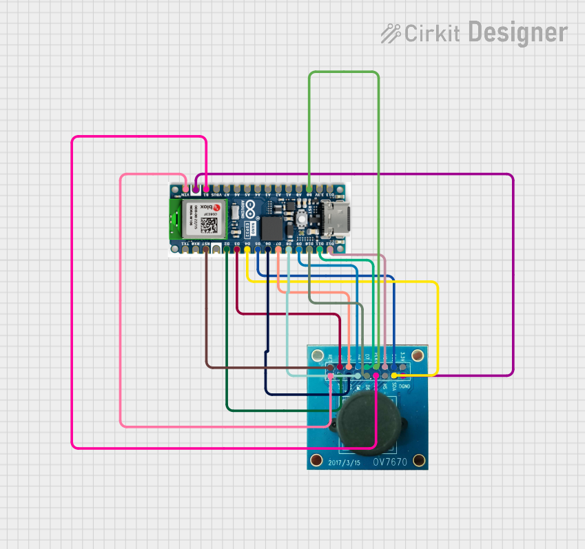
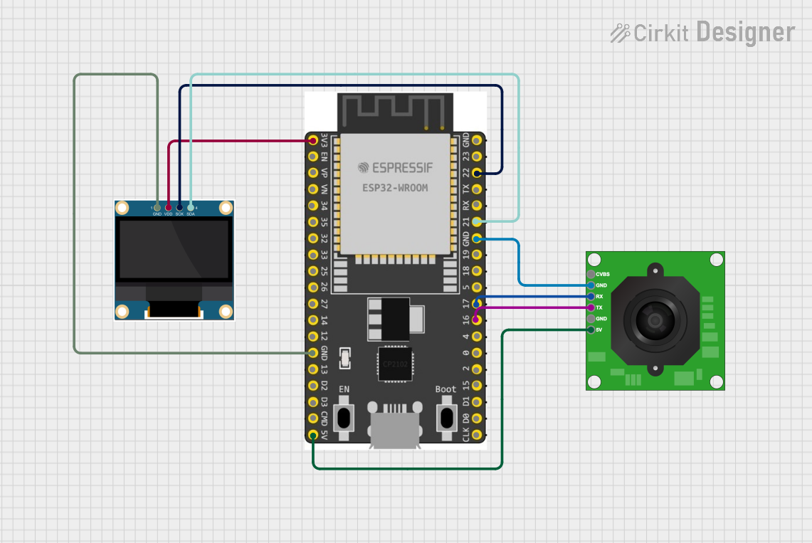


Explore Projects Built with ESP32-Cam Ov5640
Common Applications
- Home security and surveillance systems
- Smart doorbells and intercoms
- IoT-based monitoring and automation
- Face recognition and object detection projects
- Wireless image streaming for robotics and drones
Technical Specifications
Key Technical Details
| Parameter | Specification |
|---|---|
| Microcontroller | ESP32 (dual-core, 32-bit processor) |
| Image Sensor | OV5640 (5MP, 2592x1944 resolution) |
| Wireless Connectivity | Wi-Fi 802.11 b/g/n, Bluetooth 4.2 |
| Flash Memory | 4MB (PSRAM) |
| Camera Interface | DVP (Digital Video Port) |
| Operating Voltage | 3.3V |
| Power Consumption | ~160mA (active), ~10µA (deep sleep) |
| Dimensions | 27mm x 40.5mm |
| Operating Temperature | -20°C to 85°C |
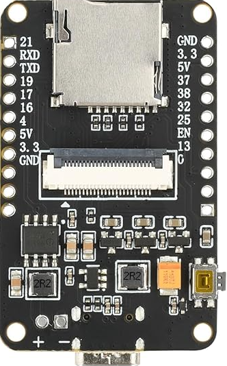
Pin Configuration and Descriptions
The ESP32-Cam Ov5640 module has a total of 16 pins. Below is the pinout and description:
| Pin Name | Pin Number | Description |
|---|---|---|
| GND | 1 | Ground |
| 3.3V | 2 | Power input (3.3V) |
| IO0 | 3 | GPIO0 (used for boot mode selection) |
| IO1 | 4 | GPIO1 (general-purpose I/O) |
| IO2 | 5 | GPIO2 (general-purpose I/O) |
| IO3 | 6 | GPIO3 (general-purpose I/O) |
| IO4 | 7 | GPIO4 (general-purpose I/O) |
| IO5 | 8 | GPIO5 (general-purpose I/O) |
| IO12 | 9 | GPIO12 (used for LED flash control) |
| IO13 | 10 | GPIO13 (general-purpose I/O) |
| IO14 | 11 | GPIO14 (general-purpose I/O) |
| IO15 | 12 | GPIO15 (general-purpose I/O) |
| IO16 | 13 | GPIO16 (general-purpose I/O) |
| IO17 | 14 | GPIO17 (general-purpose I/O) |
| RXD | 15 | UART RX (serial communication) |
| TXD | 16 | UART TX (serial communication) |
Usage Instructions
How to Use the ESP32-Cam Ov5640 in a Circuit
- Power Supply: Connect the 3.3V pin to a stable 3.3V power source and GND to ground.
- Programming Mode: To upload code, connect GPIO0 to GND and reset the module. After programming, disconnect GPIO0 from GND.
- Camera Interface: The OV5640 camera module is pre-attached. Ensure the ribbon cable is securely connected to the ESP32-Cam board.
- Serial Communication: Use the RXD and TXD pins to connect to a USB-to-serial adapter for programming and debugging.
- Wi-Fi Configuration: Configure the Wi-Fi credentials in your code to enable wireless connectivity.
Important Considerations and Best Practices
- Power Supply: Ensure a stable 3.3V power source. Voltage fluctuations can cause instability.
- Heat Management: The ESP32 may heat up during operation. Consider adding a heatsink for prolonged use.
- Antenna: For optimal Wi-Fi performance, ensure the onboard antenna is not obstructed.
- Boot Mode: Always disconnect GPIO0 from GND after uploading code to avoid boot issues.
Example Code for Arduino UNO Integration
Below is an example of how to use the ESP32-Cam Ov5640 with the Arduino IDE for basic image capture and streaming:
#include <WiFi.h>
#include <esp_camera.h>

// Replace with your Wi-Fi credentials
const char* ssid = "Your_SSID";
const char* password = "Your_PASSWORD";

// Camera configuration
#define PWDN_GPIO_NUM    -1
#define RESET_GPIO_NUM   -1
#define XCLK_GPIO_NUM     0
#define SIOD_GPIO_NUM    26
#define SIOC_GPIO_NUM    27
#define Y9_GPIO_NUM      35
#define Y8_GPIO_NUM      34
#define Y7_GPIO_NUM      39
#define Y6_GPIO_NUM      36
#define Y5_GPIO_NUM      21
#define Y4_GPIO_NUM      19
#define Y3_GPIO_NUM      18
#define Y2_GPIO_NUM       5
#define VSYNC_GPIO_NUM   25
#define HREF_GPIO_NUM    23
#define PCLK_GPIO_NUM    22

void startCameraServer();

void setup() {
  Serial.begin(115200);
  Serial.println("Initializing ESP32-Cam...");

  // Connect to Wi-Fi
  WiFi.begin(ssid, password);
  while (WiFi.status() != WL_CONNECTED) {
    delay(500);
    Serial.print(".");
  }
  Serial.println("\nWi-Fi connected!");

  // Initialize the camera
  camera_config_t config;
  config.ledc_channel = LEDC_CHANNEL_0;
  config.ledc_timer = LEDC_TIMER_0;
  config.pin_d0 = Y2_GPIO_NUM;
  config.pin_d1 = Y3_GPIO_NUM;
  config.pin_d2 = Y4_GPIO_NUM;
  config.pin_d3 = Y5_GPIO_NUM;
  config.pin_d4 = Y6_GPIO_NUM;
  config.pin_d5 = Y7_GPIO_NUM;
  config.pin_d6 = Y8_GPIO_NUM;
  config.pin_d7 = Y9_GPIO_NUM;
  config.pin_xclk = XCLK_GPIO_NUM;
  config.pin_pclk = PCLK_GPIO_NUM;
  config.pin_vsync = VSYNC_GPIO_NUM;
  config.pin_href = HREF_GPIO_NUM;
  config.pin_sscb_sda = SIOD_GPIO_NUM;
  config.pin_sscb_scl = SIOC_GPIO_NUM;
  config.pin_pwdn = PWDN_GPIO_NUM;
  config.pin_reset = RESET_GPIO_NUM;
  config.xclk_freq_hz = 20000000;
  config.pixel_format = PIXFORMAT_JPEG;

  if (!esp_camera_init(&config)) {
    Serial.println("Camera initialized successfully!");
  } else {
    Serial.println("Camera initialization failed!");
    return;
  }

  // Start the camera server
  startCameraServer();
  Serial.println("Camera server started!");
}

void loop() {
  // Main loop does nothing; camera server handles requests
}
Troubleshooting and FAQs
Common Issues and Solutions
Camera Initialization Failed:
- Ensure the ribbon cable is securely connected to the ESP32-Cam board.
- Verify that the power supply provides a stable 3.3V.
Wi-Fi Connection Issues:
- Double-check the SSID and password in your code.
- Ensure the Wi-Fi signal strength is sufficient.
Overheating:
- Add a heatsink to the ESP32 chip if it overheats during prolonged use.
Boot Mode Problems:
- Ensure GPIO0 is disconnected from GND after uploading code.
FAQs
Q: Can I use a 5V power supply?
A: No, the ESP32-Cam Ov5640 requires a 3.3V power supply. Using 5V may damage the module.Q: How do I reset the module?
A: Press the onboard reset button or momentarily disconnect the power supply.Q: Can I use this module for face recognition?
A: Yes, the ESP32-Cam Ov5640 supports face recognition and object detection with appropriate libraries.Q: What is the maximum resolution of the camera?
A: The OV5640 sensor supports up to 2592x1944 resolution (5MP).
This documentation provides a comprehensive guide to using the ESP32-Cam Ov5640 module effectively. For further assistance, refer to the manufacturer's datasheet or community forums.