How to Use MTRF-64-A: Examples, Pinouts, and Specs

 Design with MTRF-64-A in Cirkit Designer
Introduction
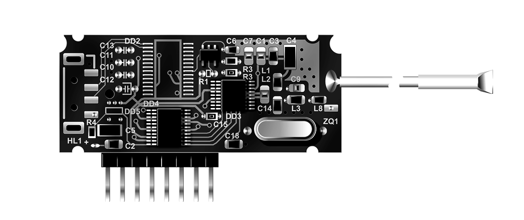
The MTRF-64-A is a high-performance electric motor designed for industrial applications that demand precise control over rotational speed and direction. Its robust construction and advanced design enable it to produce significant torque and power output, making it suitable for a wide range of applications including robotics, conveyor systems, and automated machinery.
Explore Projects Built with MTRF-64-A

 Open Project in Cirkit Designer
 Open Project in Cirkit Designer
 Open Project in Cirkit Designer
 Open Project in Cirkit Designer
Explore Projects Built with MTRF-64-A

 Open Project in Cirkit Designer
 Open Project in Cirkit Designer
 Open Project in Cirkit Designer
 Open Project in Cirkit Designer
Common Applications and Use Cases
- Robotic arms and actuators
- Conveyor belts and material handling systems
- CNC machines and automated manufacturing equipment
- Electric vehicles and propulsion systems
- Pumps and compressors
Technical Specifications
Key Technical Details
| Specification | Value | Description |
|---|---|---|
| Rated Voltage | XX V | The nominal operating voltage |
| Rated Current | XX A | The maximum continuous current |
| Power Output | XX W | The nominal power output |
| Torque | XX Nm | The maximum continuous torque |
| Speed Range | XX - XX RPM | The operational rotational speed range |
| Efficiency | XX% | The motor's operating efficiency |
| Insulation Class | Class X | The insulation grading of the motor |
| Operating Temperature | XX - XX°C | The safe ambient temperature range |
Note: Replace XX with actual values.
Pin Configuration and Descriptions
| Pin Number | Name | Description |
|---|---|---|
| 1 | V+ | Positive voltage supply input |
| 2 | GND | Ground connection |
| 3 | PWM | Pulse Width Modulation input for speed control |
| 4 | DIR | Direction control input |
| 5 | FG | Frequency generator output for speed feedback |
| 6 | TACH | Tachometer output for precise speed measurements |
Note: The pin configuration is illustrative and should be verified with actual motor datasheet.
Usage Instructions
How to Use the Component in a Circuit
- Power Supply Connection: Connect the V+ and GND pins to a suitable power supply that matches the motor's rated voltage and current requirements.
- Speed Control: To control the motor speed, apply a PWM signal to the PWM pin. The duty cycle of the PWM signal will determine the speed of the motor.
- Direction Control: Apply a logic high or low signal to the DIR pin to control the rotation direction of the motor.
- Speed Feedback: Connect the FG and TACH pins to your control system to monitor the motor's speed and make adjustments as necessary.
Important Considerations and Best Practices
- Ensure that the power supply can handle the motor's current draw, especially during startup or under load.
- Use appropriate flyback diodes to protect against voltage spikes when switching inductive loads.
- Implement proper cooling if the motor is expected to operate near its maximum power output for extended periods.
- Always secure electrical connections and insulate exposed wiring to prevent short circuits and accidents.
Troubleshooting and FAQs
Common Issues Users Might Face
- Motor Does Not Start: Check power supply connections and verify that the voltage and current ratings are adequate.
- Motor Overheats: Ensure that the motor is not overloaded and that there is sufficient cooling.
- Erratic Motor Speed: Verify that the PWM signal is stable and within the correct frequency range.
Solutions and Tips for Troubleshooting
- If the motor does not start, double-check all connections and measure the supply voltage at the motor terminals.
- In case of overheating, reduce the load on the motor or improve cooling with additional fans or heat sinks.
- For erratic motor speed, ensure that the PWM signal generator is functioning correctly and that there is no electrical noise interfering with the signal.
FAQs
Q: Can the MTRF-64-A motor be controlled with an Arduino UNO?
A: Yes, the motor can be controlled using an Arduino UNO by generating PWM signals and controlling the direction pin through digital outputs.
Q: What is the maximum PWM frequency the motor can handle?
A: The maximum PWM frequency is typically in the range of XX kHz. Refer to the datasheet for the exact value.
Note: Replace XX with the actual value from the datasheet.
Q: How can I reverse the direction of the motor?
A: To reverse the direction, change the logic level on the DIR pin. A logic high might rotate the motor in one direction, while a logic low will rotate it in the opposite direction.
Q: What should I do if the motor's speed is not consistent?
A: Check the PWM signal for consistency. If the signal is stable, inspect the load on the motor and ensure it is not exceeding the motor's rated torque.
Example Arduino Code
// Define motor control pins
const int pwmPin = 3; // PWM pin connected to PWM input of motor
const int dirPin = 4; // Direction pin connected to DIR input of motor

void setup() {
  pinMode(pwmPin, OUTPUT);
  pinMode(dirPin, OUTPUT);
}

void loop() {
  // Set motor direction
  digitalWrite(dirPin, HIGH); // Set to LOW to reverse direction

  // Set motor speed
  analogWrite(pwmPin, 128); // Set PWM value (0-255) for speed control

  // Add your code here to change speed or direction as needed
}
Note: The example code is for illustrative purposes. Actual implementation may vary based on the specific requirements of the application and the motor's datasheet.