
How to Use USB-TTL: Examples, Pinouts, and Specs
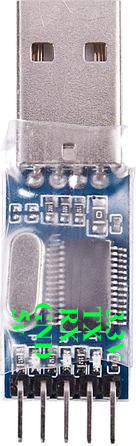
 Design with USB-TTL in Cirkit Designer
Introduction
The USB-TTL converter, manufactured by Prolific, is a versatile electronic component designed to bridge communication between USB devices and TTL (Transistor-Transistor Logic) serial devices. It is widely used in applications requiring serial communication, such as programming microcontrollers, debugging embedded systems, and interfacing with sensors or other peripherals. This compact and reliable module simplifies the process of connecting modern USB-enabled devices to legacy TTL-based systems.
Explore Projects Built with USB-TTL
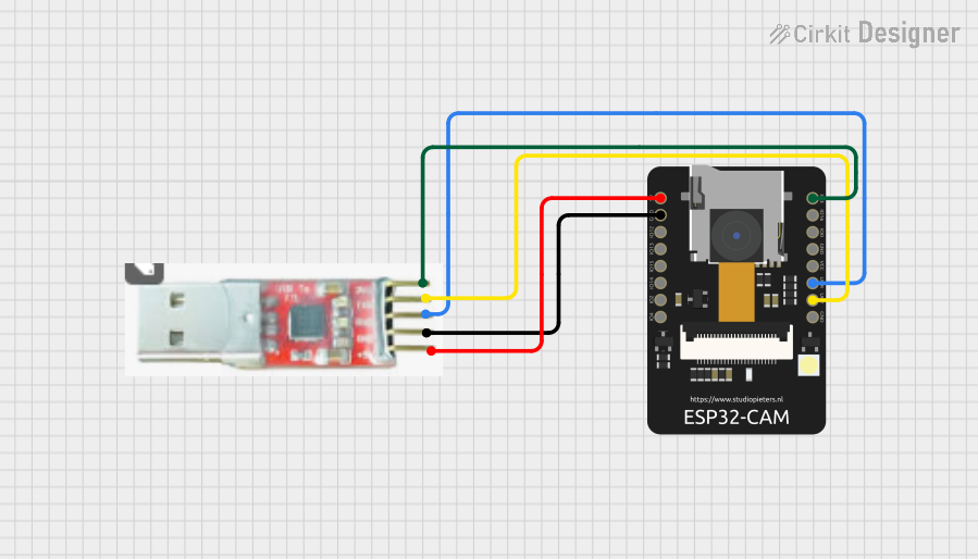 Open Project in Cirkit Designer
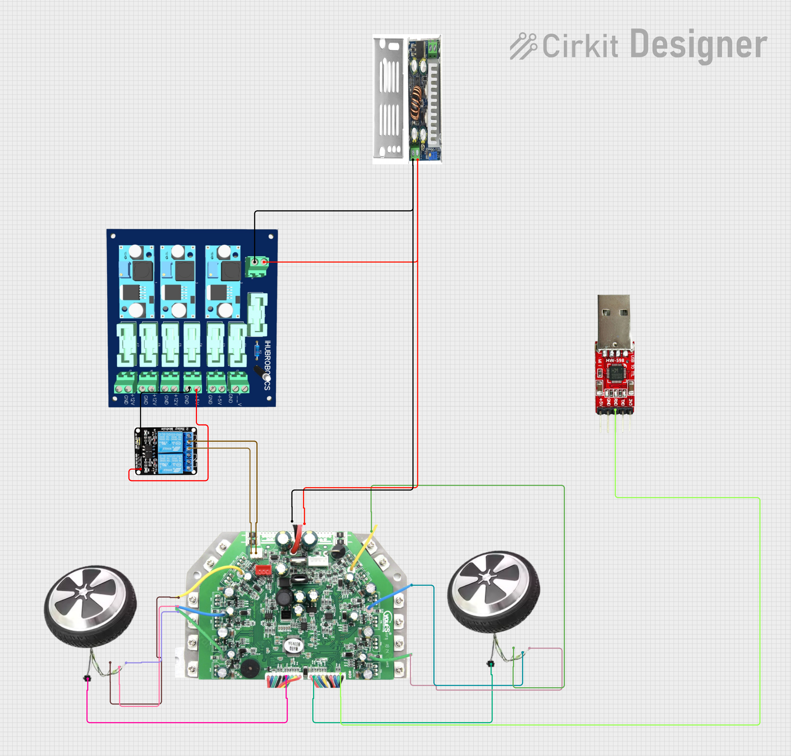 Open Project in Cirkit Designer
 Open Project in Cirkit Designer
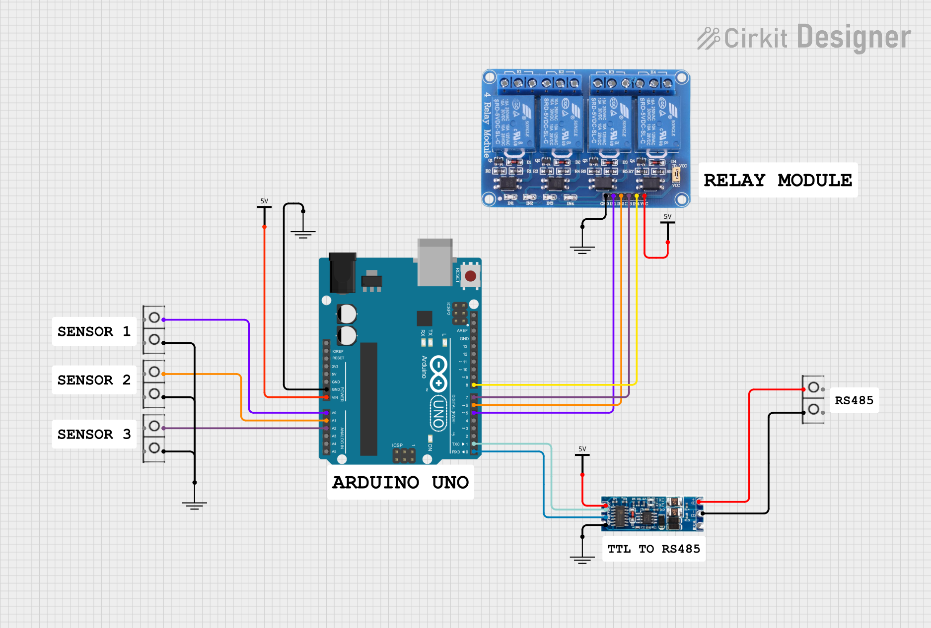 Open Project in Cirkit Designer
Explore Projects Built with USB-TTL
Open Project in Cirkit DesignerOpen Project in Cirkit DesignerOpen Project in Cirkit DesignerOpen Project in Cirkit DesignerCommon Applications and Use Cases
- Programming microcontrollers (e.g., Arduino, ESP8266, STM32)
- Debugging and monitoring serial communication
- Interfacing with sensors, modules, and other TTL devices
- Data logging and serial communication with PCs
- Prototyping and testing embedded systems
Technical Specifications
The Prolific USB-TTL converter is designed to meet the needs of a wide range of serial communication applications. Below are its key technical details:
General Specifications
- Manufacturer: Prolific
- Model: USB-TTL Converter
- Input Voltage (USB): 5V (via USB port)
- Output Voltage (TTL): 3.3V or 5V (selectable)
- Communication Protocol: UART (Universal Asynchronous Receiver-Transmitter)
- Baud Rate: 300 bps to 1 Mbps
- Operating Temperature: -40°C to 85°C
- Driver Support: Windows, macOS, Linux
Pin Configuration and Descriptions
The USB-TTL converter typically features a 6-pin header for TTL communication. Below is the pinout:
| Pin | Name | Description |
|---|---|---|
| 1 | GND | Ground connection |
| 2 | TXD | Transmit Data (output from USB-TTL to the connected device) |
| 3 | RXD | Receive Data (input from the connected device to USB-TTL) |
| 4 | VCC | Power output (3.3V or 5V, depending on the jumper setting) |
| 5 | CTS | Clear to Send (optional, used for hardware flow control) |
| 6 | RTS | Request to Send (optional, used for hardware flow control) |
Usage Instructions
How to Use the USB-TTL Converter in a Circuit
Connect the USB-TTL to Your Computer:
- Plug the USB-TTL converter into a USB port on your computer.
- Install the required Prolific drivers (available on the Prolific website) if not automatically detected.
Connect the TTL Device:
- Use jumper wires to connect the USB-TTL pins to the corresponding pins on your TTL device:
- Connect
GNDto the ground of the TTL device. - Connect
TXDto the RX pin of the TTL device. - Connect
RXDto the TX pin of the TTL device. - Optionally, connect
VCCto power the TTL device (ensure voltage compatibility).
- Connect
- Use jumper wires to connect the USB-TTL pins to the corresponding pins on your TTL device:
Set the Voltage Level:
- Use the onboard jumper to select the desired output voltage (3.3V or 5V) based on your TTL device's requirements.
Open a Serial Communication Tool:
- Use software like Arduino IDE, PuTTY, or a custom serial terminal to communicate with the TTL device.
- Select the correct COM port and baud rate in the software.
Test the Connection:
- Send and receive data to verify communication between the USB-TTL and the TTL device.
Important Considerations and Best Practices
- Voltage Compatibility: Ensure the voltage level (3.3V or 5V) matches the requirements of your TTL device to avoid damage.
- Cross-Connection: Always connect
TXDto the RX pin andRXDto the TX pin of the TTL device. - Driver Installation: Install the latest Prolific drivers to ensure compatibility with your operating system.
- Avoid Overloading: Do not draw excessive current from the
VCCpin, as it is limited by the USB port's power supply.
Example: Connecting USB-TTL to Arduino UNO
Below is an example of using the USB-TTL converter to communicate with an Arduino UNO:
Circuit Connections
| USB-TTL Pin | Arduino UNO Pin |
|---|---|
| GND | GND |
| TXD | RX (Pin 0) |
| RXD | TX (Pin 1) |
Arduino Code Example
// Example code to send and receive data via USB-TTL
void setup() {
  Serial.begin(9600); // Initialize serial communication at 9600 baud
  Serial.println("USB-TTL Communication Initialized");
}

void loop() {
  if (Serial.available() > 0) {
    // Read incoming data from USB-TTL
    char received = Serial.read();
    Serial.print("Received: ");
    Serial.println(received); // Echo the received data
  }
  delay(100); // Small delay to avoid flooding the serial buffer
}
Troubleshooting and FAQs
Common Issues and Solutions
No Communication Detected:
- Cause: Incorrect COM port or baud rate.
- Solution: Verify the COM port in your serial terminal and ensure the baud rate matches the TTL device's settings.
Device Not Recognized by Computer:
- Cause: Missing or outdated drivers.
- Solution: Download and install the latest Prolific drivers from the official website.
Data Corruption or Noise:
- Cause: Mismatched voltage levels or loose connections.
- Solution: Ensure proper voltage selection and secure all connections.
TTL Device Not Responding:
- Cause: Incorrect TXD/RXD connections.
- Solution: Double-check that
TXDis connected to the RX pin andRXDto the TX pin.
FAQs
Q: Can I use the USB-TTL converter to power my TTL device?
A: Yes, but ensure the device's current requirements do not exceed the USB-TTL's power output capacity.Q: What is the maximum baud rate supported?
A: The USB-TTL converter supports baud rates up to 1 Mbps.Q: Is the USB-TTL compatible with macOS?
A: Yes, the Prolific USB-TTL converter is compatible with macOS, but you may need to install the appropriate drivers.Q: Can I use this converter for RS232 devices?
A: No, the USB-TTL converter is designed for TTL-level signals (3.3V or 5V) and is not compatible with RS232 voltage levels.
By following this documentation, you can effectively use the Prolific USB-TTL converter for a wide range of serial communication applications.