
How to Use Power Jack: Examples, Pinouts, and Specs
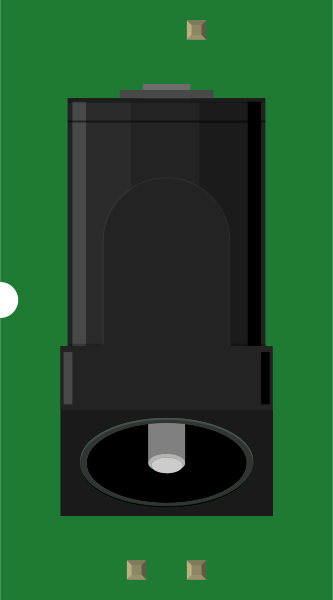
 Design with Power Jack in Cirkit Designer
Introduction
The Power Jack (Manufacturer: SparkFun, Part ID: PRT-00119) is a socket designed to connect an external power supply to an electronic device. It serves as a reliable interface for delivering electrical power, ensuring stable operation of the connected circuit or device. This component is commonly used in projects requiring a DC power source, such as Arduino-based systems, robotics, and other embedded electronics.
Explore Projects Built with Power Jack
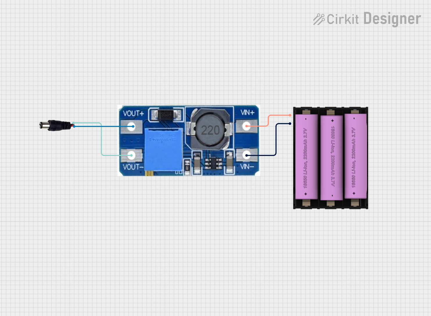 Open Project in Cirkit Designer
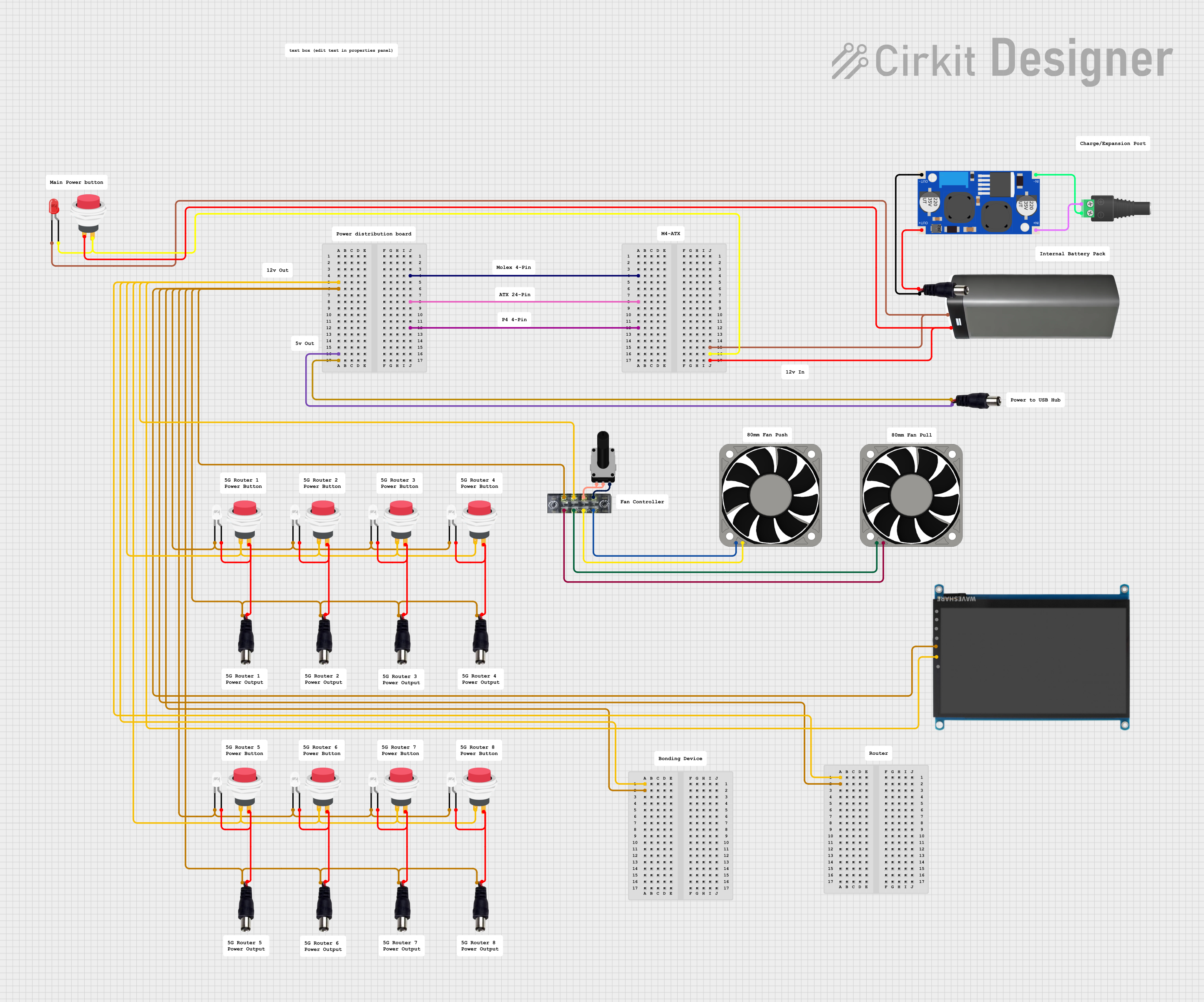 Open Project in Cirkit Designer
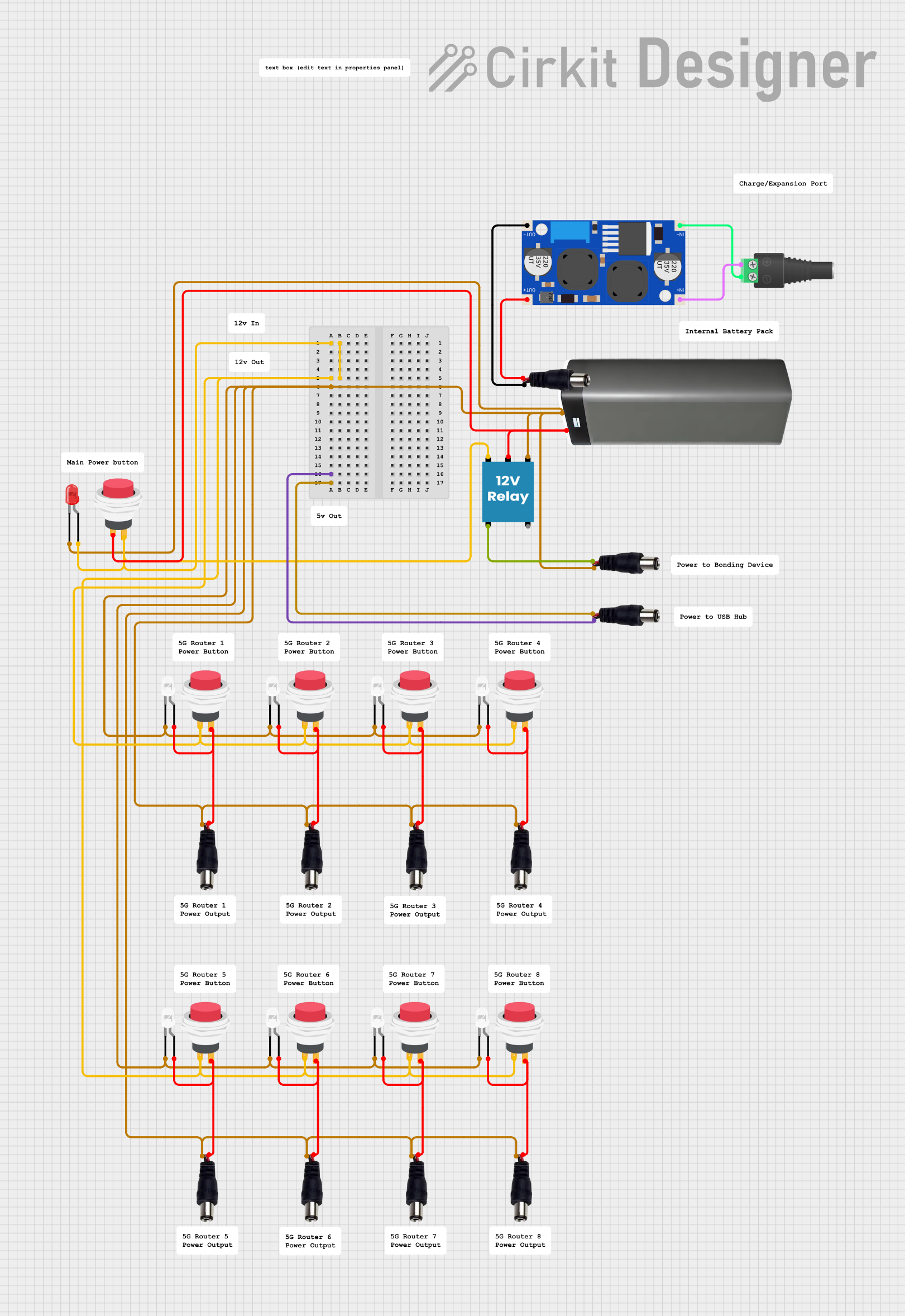 Open Project in Cirkit Designer
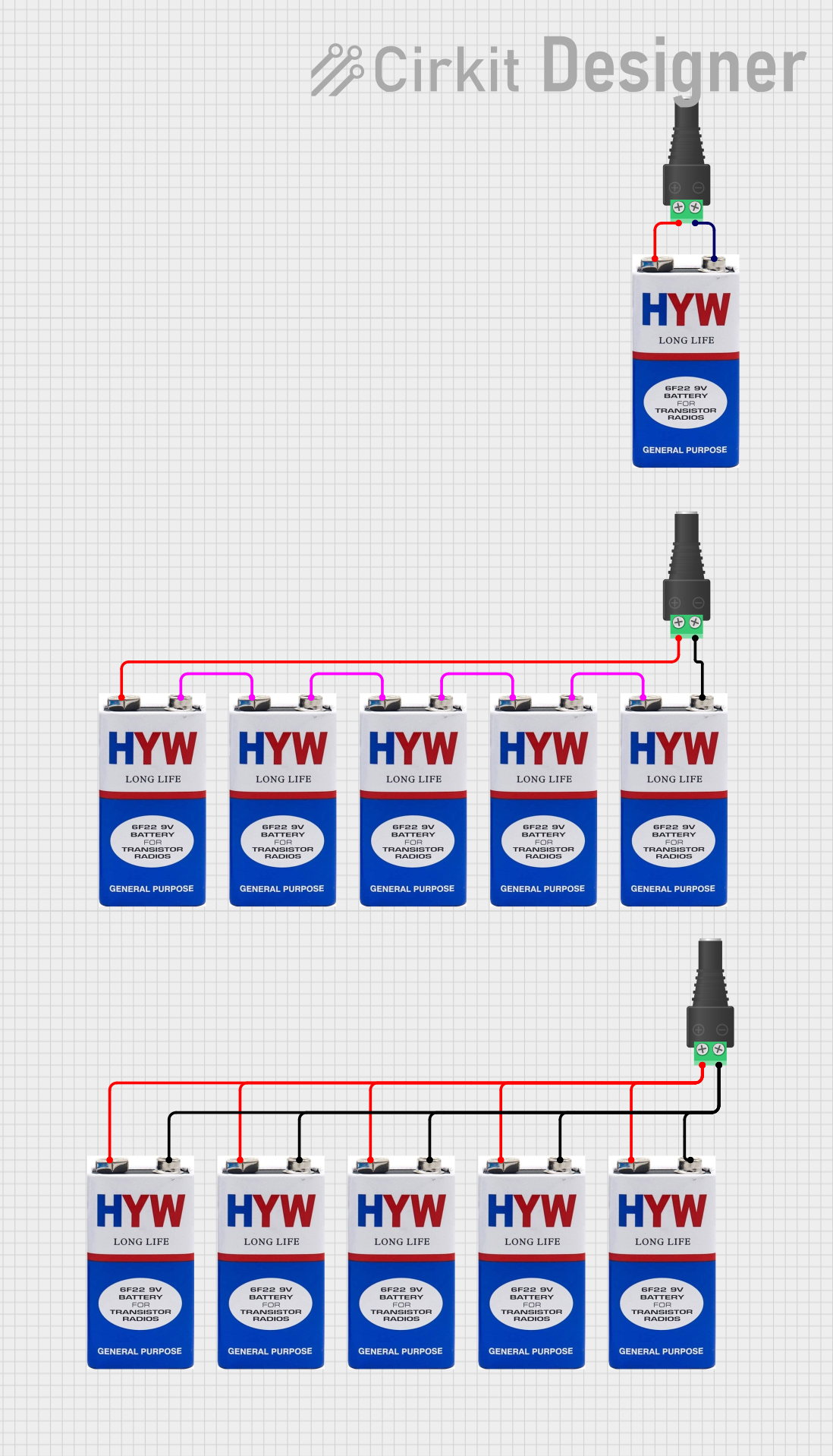 Open Project in Cirkit Designer
Explore Projects Built with Power Jack
Open Project in Cirkit DesignerOpen Project in Cirkit DesignerOpen Project in Cirkit DesignerOpen Project in Cirkit DesignerCommon Applications and Use Cases
- Powering microcontroller boards (e.g., Arduino, Raspberry Pi with adapters)
- Robotics and automation systems
- Consumer electronics requiring external DC power
- Prototyping and DIY electronics projects
Technical Specifications
The following table outlines the key technical details of the SparkFun Power Jack (PRT-00119):
| Parameter | Specification |
|---|---|
| Manufacturer | SparkFun |
| Part ID | PRT-00119 |
| Connector Type | Barrel Jack (Female) |
| Barrel Dimensions | 5.5 mm outer diameter, 2.1 mm inner diameter |
| Voltage Rating | Up to 24V DC |
| Current Rating | Up to 5A |
| Mounting Style | Through-hole |
| Material | Plastic housing with metal contacts |
| Operating Temperature | -40°C to +85°C |
Pin Configuration and Descriptions
The Power Jack has three pins, as described in the table below:
| Pin | Name | Description |
|---|---|---|
| 1 | Positive (V+) | Connects to the positive terminal of the DC power supply. |
| 2 | Negative (V-) | Connects to the negative terminal (ground) of the DC power supply. |
| 3 | Switch Pin | Optional pin that disconnects when a plug is inserted, useful for power control. |
Usage Instructions
How to Use the Power Jack in a Circuit
Mounting the Power Jack:
- Solder the three pins of the Power Jack onto a PCB using the through-hole mounting style.
- Ensure the pins are securely soldered to avoid loose connections.
Connecting Power:
- Connect the Positive (V+) pin to the positive rail of your circuit.
- Connect the Negative (V-) pin to the ground rail of your circuit.
- If using the Switch Pin, connect it to a circuit element that needs to be disconnected when a plug is inserted.
Selecting a Compatible Plug:
- Use a DC barrel plug with a 5.5 mm outer diameter and 2.1 mm inner diameter.
- Ensure the plug's voltage and current ratings match the requirements of your circuit.
Testing the Connection:
- Before powering the circuit, verify the polarity and ensure there are no short circuits.
- Use a multimeter to confirm proper voltage levels at the output.
Important Considerations and Best Practices
- Polarity: Always double-check the polarity of the power supply to avoid damaging your circuit.
- Voltage and Current Ratings: Ensure the input voltage and current do not exceed the Power Jack's maximum ratings (24V DC, 5A).
- Heat Dissipation: For high-current applications, ensure proper ventilation to prevent overheating.
- Switch Pin Usage: If not used, leave the switch pin unconnected or grounded, depending on your circuit design.
Example: Connecting to an Arduino UNO
The Power Jack can be used to power an Arduino UNO by connecting a 9V DC adapter. Below is an example Arduino sketch to test the setup:
// Example Arduino code to blink an LED when powered via the Power Jack
// Ensure the Power Jack is connected to a 9V DC adapter

const int ledPin = 13; // Built-in LED pin on Arduino UNO

void setup() {
  pinMode(ledPin, OUTPUT); // Set the LED pin as an output
}

void loop() {
  digitalWrite(ledPin, HIGH); // Turn the LED on
  delay(1000);               // Wait for 1 second
  digitalWrite(ledPin, LOW);  // Turn the LED off
  delay(1000);               // Wait for 1 second
}
Troubleshooting and FAQs
Common Issues and Solutions
No Power to the Circuit:
- Cause: Loose connection or incorrect polarity.
- Solution: Check the solder joints and ensure the power supply polarity matches the circuit.
Overheating of the Power Jack:
- Cause: Exceeding the current rating (5A).
- Solution: Use a power supply within the specified current range and ensure proper ventilation.
Intermittent Power Loss:
- Cause: Poor contact between the barrel plug and the Power Jack.
- Solution: Use a high-quality barrel plug and ensure it fits snugly into the Power Jack.
Switch Pin Not Functioning:
- Cause: Incorrect wiring or unused pin.
- Solution: Verify the switch pin connection and ensure it is properly integrated into the circuit.
FAQs
Q1: Can I use the Power Jack with an AC adapter?
A1: No, the Power Jack is designed for DC power only. Using an AC adapter may damage your circuit.
Q2: What is the recommended voltage for powering an Arduino UNO using this Power Jack?
A2: A 9V DC adapter is recommended for powering an Arduino UNO through the Power Jack.
Q3: Can I use the Power Jack for high-power applications?
A3: The Power Jack supports up to 24V DC and 5A. For higher power requirements, consider using a more robust connector.
Q4: Is the Power Jack waterproof?
A4: No, the Power Jack is not waterproof. Use it in dry environments or enclosures to protect it from moisture.
By following this documentation, you can effectively integrate the SparkFun Power Jack (PRT-00119) into your electronic projects.