How to Use SparkFun USB UART Breakout - CY7C65213: Examples, Pinouts, and Specs
Introduction
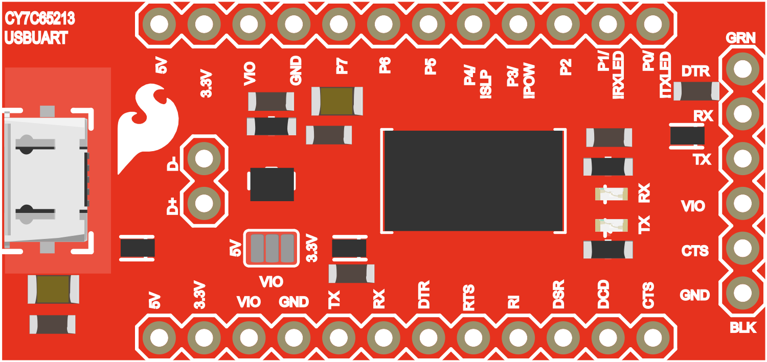
The SparkFun USB UART Breakout featuring the CY7C65213 is a compact and versatile USB to UART converter module. This component is essential for projects that require a bridge between USB communications and serial UART interfaces, commonly found in microcontrollers and other serial devices. It is widely used for serial communication, debugging, and programming hardware through a USB interface.
Explore Projects Built with SparkFun USB UART Breakout - CY7C65213
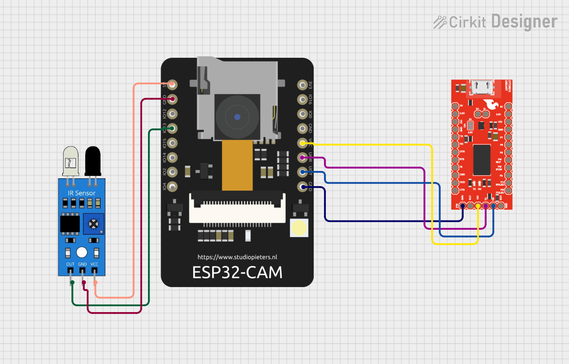

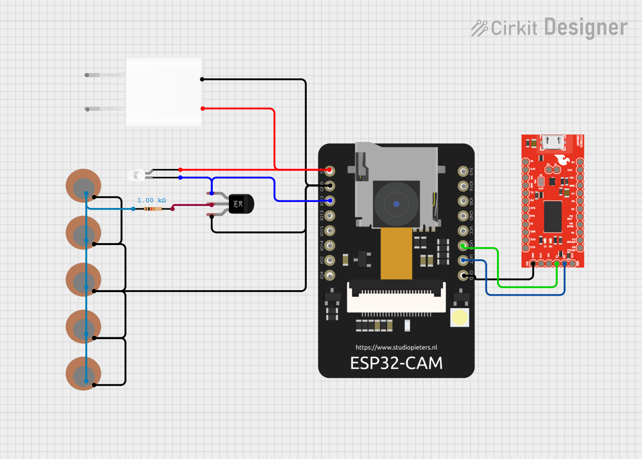

Explore Projects Built with SparkFun USB UART Breakout - CY7C65213
Common Applications and Use Cases
- Serial communication with microcontrollers
- USB to serial conversions for debugging purposes
- Programming devices without a dedicated USB interface
- Bridging communication between a PC and a serial device
Technical Specifications
Key Technical Details
- USB Interface: USB 2.0 Full-Speed Compatible
- UART Interface: Supports UART signaling with baud rates from 300 bps to 3 Mbps
- Voltage Levels: 3.3V logic level (5V tolerant)
- Current Rating: 25 mA drive strength on UART interface pins
- Operating Temperature: -40°C to +85°C
Pin Configuration and Descriptions
| Pin Number | Name | Type | Description |
|---|---|---|---|
| 1 | GND | Power | Ground connection |
| 2 | CTS | Input | Clear to Send, UART flow control |
| 3 | VCC | Power | Power supply (3.3V to 5V) |
| 4 | TXD | Output | Transmit Data, UART transmit signal |
| 5 | RXD | Input | Receive Data, UART receive signal |
| 6 | DTR | Output | Data Terminal Ready, control signal |
| 7 | DSR | Input | Data Set Ready, control signal |
| 8 | RI | Input | Ring Indicator, control signal |
| 9 | NC | - | No Connection |
Usage Instructions
How to Use the Component in a Circuit
- Powering the Module: Connect the VCC pin to a 3.3V or 5V power supply, and the GND pin to the ground.
- Connecting UART Lines: Connect the TXD pin of the module to the RXD pin of your microcontroller and the RXD pin to the TXD pin of the microcontroller.
- Flow Control (Optional): If required, connect the CTS and DTR pins for hardware flow control.
- USB Connection: Connect the module to a computer using a USB cable. The computer should recognize the device and assign a COM port.
Important Considerations and Best Practices
- Ensure that the power supply voltage matches the requirements of the module (3.3V to 5V).
- Always cross-connect TXD and RXD lines—TXD to RXD and RXD to TXD.
- Use proper ESD precautions when handling the module to prevent damage.
- Install the necessary drivers for the CY7C65213 chip on your computer to ensure proper communication.
- For Arduino users, select the correct COM port in the Arduino IDE when programming or communicating with the board.
Troubleshooting and FAQs
Common Issues
- Device Not Recognized: Ensure that the drivers are installed correctly and that the USB cable is functioning.
- No Communication: Check the TXD and RXD connections, and ensure that the baud rates of the module and the microcontroller match.
- Intermittent Communication: Verify that there is no power supply instability and that the flow control settings are correct if used.
Solutions and Tips for Troubleshooting
- Driver Installation: Visit the SparkFun or Cypress website to download and install the latest drivers for the CY7C65213 chip.
- Cable Check: Use a different USB cable to rule out cable issues.
- Baud Rate Matching: Double-check the baud rate settings in your software and ensure they match the settings of the device you're communicating with.
FAQs
Q: Can I use this module with a 5V microcontroller? A: Yes, the module is 5V tolerant, but ensure that the VCC is supplied with the correct voltage.
Q: What operating systems are compatible with this module? A: The module is compatible with Windows, macOS, and Linux, but ensure that the appropriate drivers are installed.
Q: How do I change the baud rate? A: The baud rate can be changed through the serial communication software or by configuring the UART settings in your microcontroller code.
Q: Does the module require any external software? A: No external software is required for basic operation, but drivers are needed for the module to be recognized by your computer.
For further assistance, consult the SparkFun forums or the Cypress CY7C65213 datasheet for more detailed information.