How to Use Toggle Switch: Examples, Pinouts, and Specs
Introduction
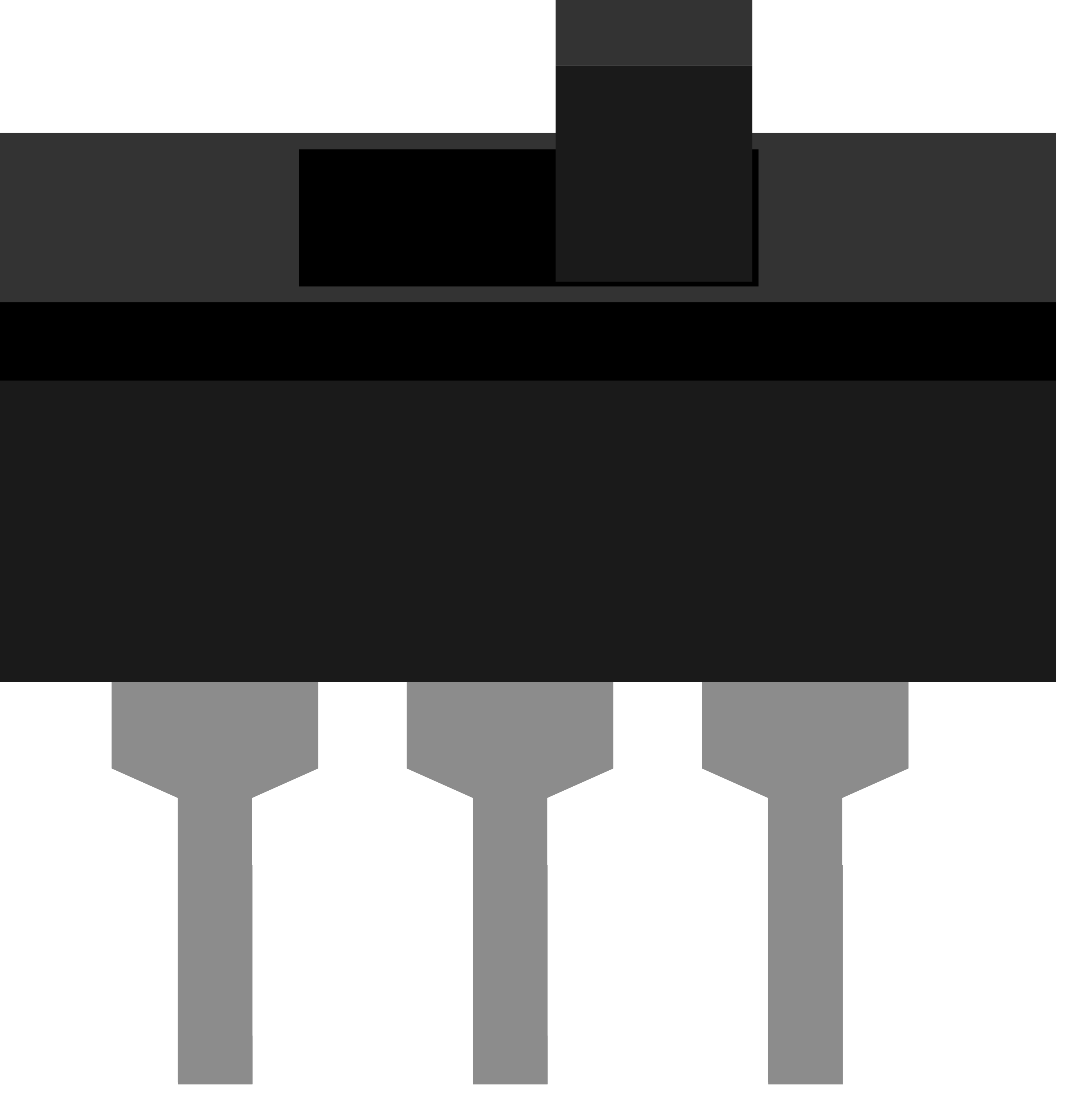
A toggle switch is a class of electrical switches that are manually actuated by a mechanical lever, handle, or rocking mechanism. Toggle switches are widely used in various applications ranging from industrial equipment to consumer electronics. They provide a simple and effective way to open or close an electrical circuit, allowing for the control of power and signal flow in a system.
Explore Projects Built with Toggle Switch

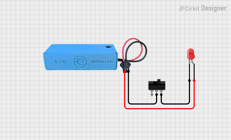
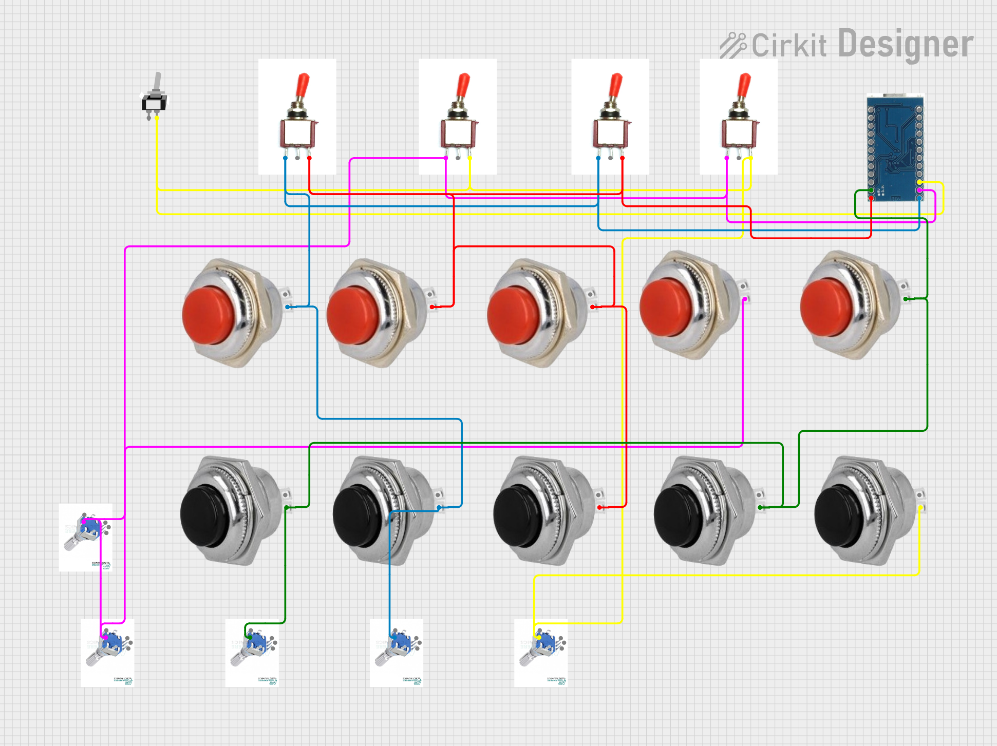
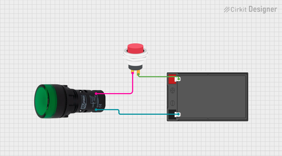
Explore Projects Built with Toggle Switch
Common Applications and Use Cases
- Power control in household appliances
- On/off switching for lighting fixtures
- Control panels in industrial machinery
- Automotive switches for headlights and accessories
- User interface for electronic devices
Technical Specifications
Key Technical Details
- Voltage Rating: The maximum voltage the switch can handle.
- Current Rating: The maximum current the switch can conduct.
- Power Rating: The maximum power the switch can handle.
- Contact Configuration: Typically SPST (Single Pole Single Throw), SPDT (Single Pole Double Throw), DPST (Double Pole Single Throw), or DPDT (Double Pole Double Throw).
- Switching Mechanism: The method by which the switch changes states (e.g., break-before-make, make-before-break).
- Mechanical Life: The number of actuations the switch can withstand before failure.
Pin Configuration and Descriptions
| Pin Number | Description | Notes |
|---|---|---|
| 1 | Common terminal (COM) | Connects to the circuit's power or signal source |
| 2 | Normally Open (NO) terminal | Connected to COM when the switch is in the ON position |
| 3 | Normally Closed (NC) terminal | Connected to COM when the switch is in the OFF position (only present in SPDT and DPDT switches) |
Note: The pin configuration may vary depending on the type of toggle switch (e.g., SPST, SPDT, DPST, DPDT).
Usage Instructions
How to Use the Toggle Switch in a Circuit
- Identify the Type of Toggle Switch: Determine whether you have an SPST, SPDT, DPST, or DPDT switch based on your application needs.
- Connect the Common Terminal: The COM terminal should be connected to the power or signal source you wish to control.
- Connect the Output Terminals: For an SPST switch, connect the NO terminal to the load. For SPDT and other types, choose the appropriate terminal based on the desired switch position.
- Secure the Switch: Mount the toggle switch to your panel or enclosure, ensuring a firm fit to prevent movement during operation.
- Test the Switch: Before applying power, manually actuate the switch to ensure it moves freely and settles into each position.
Important Considerations and Best Practices
- Ensure the switch's voltage and current ratings are suitable for your application.
- Use a switch with a power rating higher than the maximum power expected in the circuit.
- Avoid excessive force when actuating the switch to prevent mechanical damage.
- If the switch is used in a high-vibration environment, consider using locking washers to maintain terminal connections.
Troubleshooting and FAQs
Common Issues
- Switch Does Not Operate: Check for mechanical obstructions or damage to the lever.
- Intermittent Connection: Inspect the terminals for loose connections or corrosion.
- Overheating: Ensure the current through the switch does not exceed its rating.
Solutions and Tips for Troubleshooting
- If the switch lever is stuck, gently attempt to move it back and forth to dislodge any obstruction.
- Tighten terminal screws and apply contact cleaner to address connection issues.
- If overheating occurs, disconnect the switch and check the current draw of the circuit. Replace the switch with one that has a higher current rating if necessary.
FAQs
Q: Can I use a toggle switch with an Arduino? A: Yes, toggle switches can be used with an Arduino to control digital inputs.
Q: How do I know if my toggle switch is on or off? A: Typically, the ON position is when the lever is pushed towards the terminals, but this can vary. Check the switch's datasheet for the specific ON/OFF orientation.
Q: What is the difference between SPST and DPDT switches? A: An SPST switch has one circuit that can be opened or closed, while a DPDT switch can control two separate circuits and has two positions to route each circuit differently.
Example Code for Arduino UNO
Below is an example of how to use a toggle switch with an Arduino UNO to control an LED.
// Define the pin numbers
const int switchPin = 2; // Toggle switch connected to digital pin 2
const int ledPin = 13;   // Onboard LED connected to digital pin 13

void setup() {
  pinMode(switchPin, INPUT_PULLUP); // Set the switch pin as an input with internal pull-up resistor
  pinMode(ledPin, OUTPUT);          // Set the LED pin as an output
}

void loop() {
  // Read the state of the toggle switch
  int switchState = digitalRead(switchPin);

  // If the switch is in the ON position (assuming LOW is ON)
  if (switchState == LOW) {
    digitalWrite(ledPin, HIGH); // Turn on the LED
  } else {
    digitalWrite(ledPin, LOW);  // Turn off the LED
  }
}
Note: The INPUT_PULLUP mode is used to enable the internal pull-up resistor, which ensures a default HIGH state when the switch is open (OFF position). When the switch is closed (ON position), the pin is pulled LOW.
Remember to adjust the pin numbers and logic according to your specific circuit and switch type.