How to Use Freenove ESP32-E 40pin: Examples, Pinouts, and Specs
Introduction
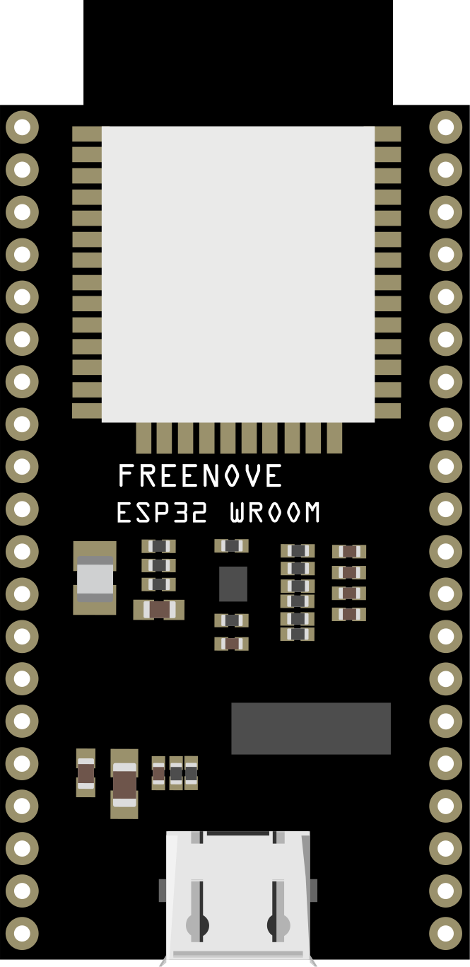
The Freenove ESP32-E 40pin is a versatile microcontroller board based on the powerful ESP32 chip. It features 40 pins for a wide range of input/output (I/O) connections, making it suitable for complex projects. With built-in Wi-Fi and Bluetooth capabilities, this board is ideal for Internet of Things (IoT) applications, smart devices, and embedded systems. Its compact design and robust functionality make it a popular choice for both hobbyists and professionals.
Explore Projects Built with Freenove ESP32-E 40pin


Explore Projects Built with Freenove ESP32-E 40pin
Common Applications and Use Cases
- IoT devices and smart home automation
- Wireless sensor networks
- Robotics and motor control
- Data logging and remote monitoring
- Prototyping and educational projects
Technical Specifications
Key Technical Details
- Microcontroller: ESP32 dual-core processor
- Clock Speed: Up to 240 MHz
- Flash Memory: 4 MB
- SRAM: 520 KB
- Connectivity: Wi-Fi (802.11 b/g/n), Bluetooth 4.2 (Classic and BLE)
- Operating Voltage: 3.3V
- Input Voltage Range: 5V (via USB) or 7-12V (via VIN pin)
- GPIO Pins: 34 (configurable as digital I/O, PWM, ADC, etc.)
- ADC Channels: 18 (12-bit resolution)
- DAC Channels: 2 (8-bit resolution)
- UART Interfaces: 3
- SPI Interfaces: 2
- I2C Interfaces: 2
- Power Consumption: Ultra-low power consumption in deep sleep mode (~10 µA)
Pin Configuration and Descriptions
The Freenove ESP32-E 40pin has a total of 40 pins, each with specific functions. Below is a summary of the pin configuration:
| Pin Name | Function | Description |
|---|---|---|
| VIN | Power Input | Accepts 7-12V input to power the board. |
| GND | Ground | Common ground for the circuit. |
| 3V3 | Power Output | Provides 3.3V output for external components. |
| EN | Enable | Resets the chip when pulled low. |
| IO0 | GPIO0 / Boot Mode | Used for boot mode selection or general-purpose I/O. |
| IO2 | GPIO2 | General-purpose I/O pin. |
| IO4 | GPIO4 | General-purpose I/O pin. |
| IO5 | GPIO5 | General-purpose I/O pin. |
| IO12 | GPIO12 / ADC / Touch | Configurable as ADC, touch input, or general-purpose I/O. |
| IO13 | GPIO13 / ADC / Touch | Configurable as ADC, touch input, or general-purpose I/O. |
| IO14 | GPIO14 / ADC / Touch | Configurable as ADC, touch input, or general-purpose I/O. |
| IO15 | GPIO15 / ADC / Touch | Configurable as ADC, touch input, or general-purpose I/O. |
| IO16 | GPIO16 | General-purpose I/O pin. |
| IO17 | GPIO17 | General-purpose I/O pin. |
| IO18 | GPIO18 / SPI_CLK | Configurable as SPI clock or general-purpose I/O. |
| IO19 | GPIO19 / SPI_MISO | Configurable as SPI MISO or general-purpose I/O. |
| IO21 | GPIO21 / I2C_SDA | Configurable as I2C SDA or general-purpose I/O. |
| IO22 | GPIO22 / I2C_SCL | Configurable as I2C SCL or general-purpose I/O. |
| IO23 | GPIO23 / SPI_MOSI | Configurable as SPI MOSI or general-purpose I/O. |
| IO25 | GPIO25 / DAC1 | Configurable as DAC output or general-purpose I/O. |
| IO26 | GPIO26 / DAC2 | Configurable as DAC output or general-purpose I/O. |
| IO27 | GPIO27 | General-purpose I/O pin. |
| IO32 | GPIO32 / ADC / Touch | Configurable as ADC, touch input, or general-purpose I/O. |
| IO33 | GPIO33 / ADC / Touch | Configurable as ADC, touch input, or general-purpose I/O. |
| IO34 | GPIO34 / ADC | Input-only ADC pin. |
| IO35 | GPIO35 / ADC | Input-only ADC pin. |
Note: Not all GPIO pins support all functions simultaneously. Refer to the ESP32 datasheet for detailed pin multiplexing information.
Usage Instructions
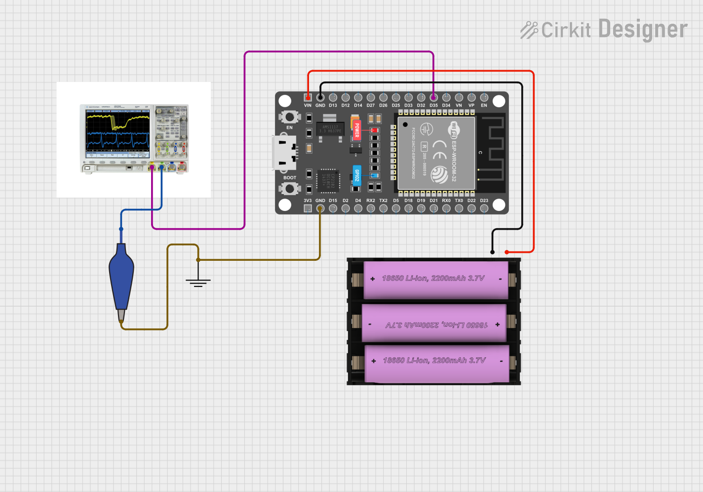
How to Use the Component in a Circuit
- Powering the Board:
- Use a USB cable to power the board via the micro-USB port (5V input).
- Alternatively, supply 7-12V to the VIN pin for external power.
- Connecting Peripherals:
- Use the GPIO pins to connect sensors, actuators, or other devices.
- Ensure the voltage levels of connected devices are compatible with the 3.3V logic of the ESP32.
- Programming the Board:
- Install the Arduino IDE and add the ESP32 board support package.
- Connect the board to your computer via USB and select the appropriate COM port.
- Write and upload your code to the board.
Important Considerations and Best Practices
- Voltage Levels: The GPIO pins operate at 3.3V. Avoid connecting 5V signals directly to the pins to prevent damage.
- Boot Mode: Ensure GPIO0 is not pulled high during boot to avoid entering programming mode unintentionally.
- Power Supply: Use a stable power source to avoid unexpected resets or instability.
- Deep Sleep Mode: Utilize the deep sleep mode for battery-powered applications to minimize power consumption.
Example Code for Arduino UNO Integration
Below is an example of how to blink an LED connected to GPIO2:
// Example: Blink an LED connected to GPIO2 on the Freenove ESP32-E 40pin

#define LED_PIN 2  // GPIO2 is connected to the LED

void setup() {
  pinMode(LED_PIN, OUTPUT);  // Set GPIO2 as an output pin
}

void loop() {
  digitalWrite(LED_PIN, HIGH);  // Turn the LED on
  delay(1000);                  // Wait for 1 second
  digitalWrite(LED_PIN, LOW);   // Turn the LED off
  delay(1000);                  // Wait for 1 second
}
Tip: Use the Serial Monitor in the Arduino IDE to debug your code and monitor outputs.
Troubleshooting and FAQs
Common Issues and Solutions
Board Not Detected by Computer:
- Ensure the USB cable is functional and supports data transfer.
- Install the correct USB-to-serial driver for the ESP32.
Upload Fails with "Failed to Connect" Error:
- Press and hold the "BOOT" button on the board while uploading the code.
Wi-Fi Connection Issues:
- Verify the SSID and password in your code.
- Ensure the router is within range and supports 2.4 GHz Wi-Fi.
Unstable Operation or Random Resets:
- Check the power supply for stability.
- Avoid excessive current draw from the GPIO pins.
FAQs
Q: Can I use 5V sensors with this board?
A: Yes, but you will need a level shifter to convert 5V signals to 3.3V.Q: How do I reset the board?
A: Press the "EN" button to reset the board.Q: Can I use this board with MicroPython?
A: Yes, the ESP32 is compatible with MicroPython. Flash the firmware to get started.
By following this documentation, you can effectively utilize the Freenove ESP32-E 40pin for your projects.