
How to Use GP-2106: Examples, Pinouts, and Specs

 Design with GP-2106 in Cirkit Designer
Introduction
The GP-2106 is a general-purpose integrated circuit (IC) designed for a wide range of applications, including signal processing, control systems, and general electronic designs. Its versatility, reliability, and ease of integration make it a popular choice for both hobbyists and professional engineers. The GP-2106 features multiple input/output pins, allowing it to interface seamlessly with other components in complex circuits.
Explore Projects Built with GP-2106
 Open Project in Cirkit Designer
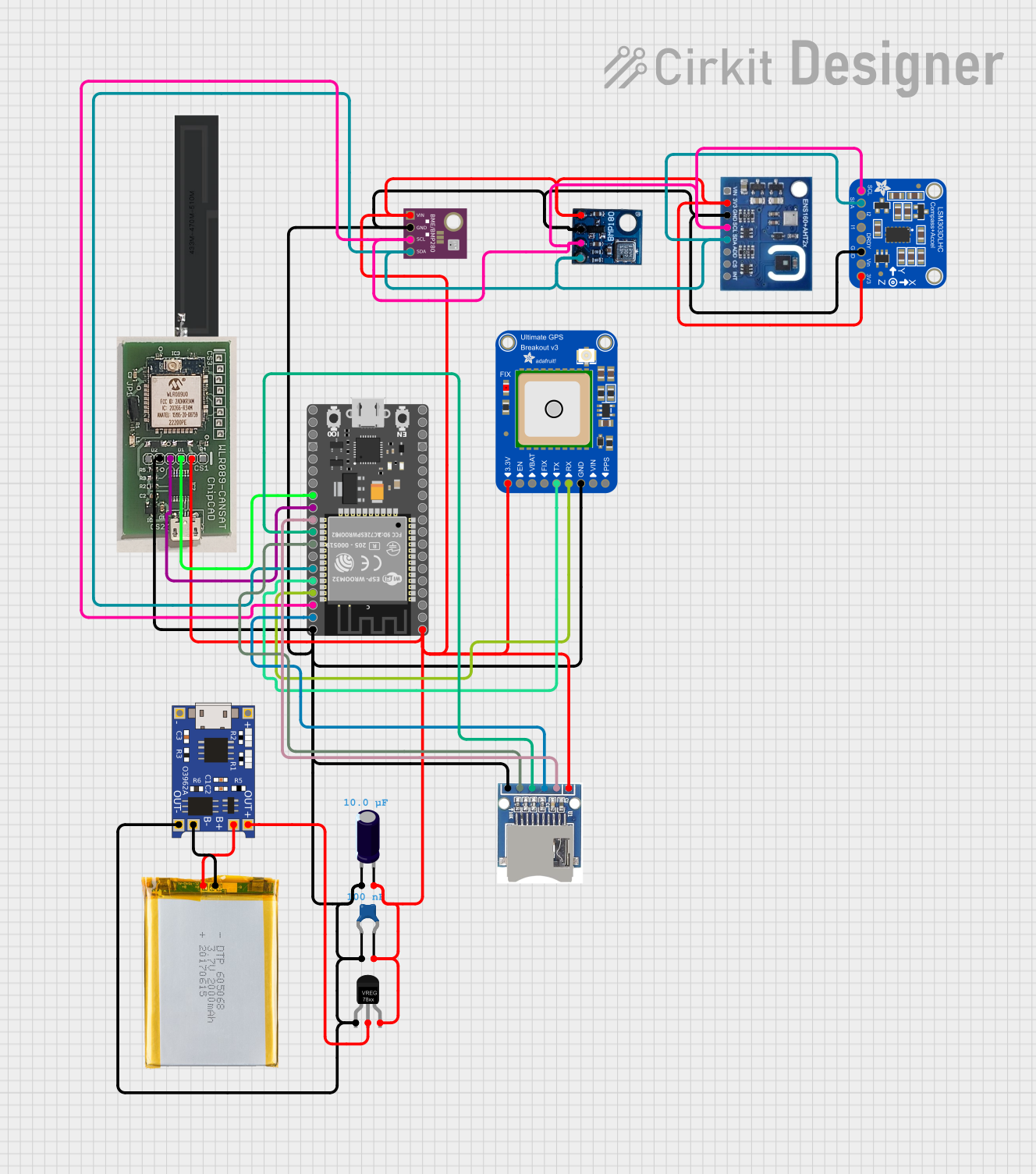 Open Project in Cirkit Designer
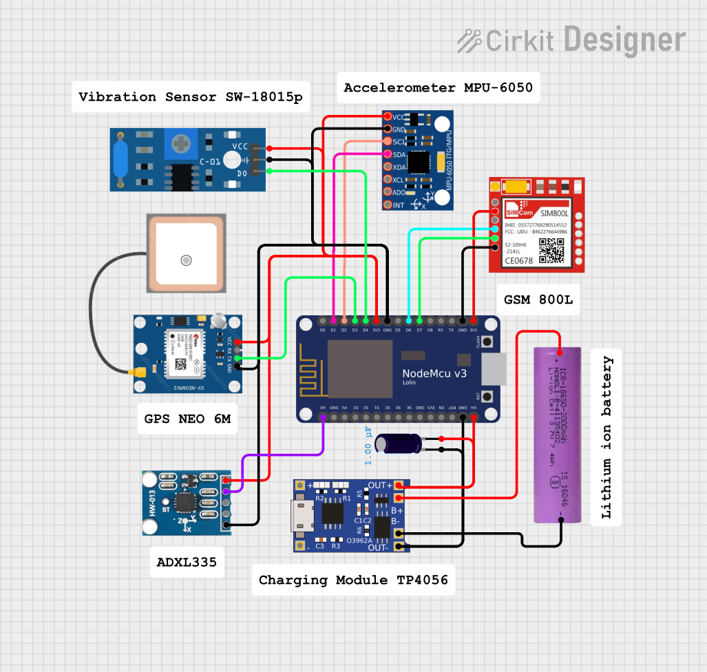 Open Project in Cirkit Designer
 Open Project in Cirkit Designer
Explore Projects Built with GP-2106
Open Project in Cirkit DesignerOpen Project in Cirkit DesignerOpen Project in Cirkit DesignerOpen Project in Cirkit DesignerCommon Applications
- Signal processing in audio and communication systems
- Control systems for industrial automation
- General-purpose logic and switching circuits
- Prototyping and educational projects
Technical Specifications
The GP-2106 is designed to operate efficiently in various environments. Below are its key technical details:
Key Specifications
| Parameter | Value |
|---|---|
| Operating Voltage | 3.3V to 5V |
| Maximum Current | 20 mA per pin |
| Power Dissipation | 500 mW |
| Operating Temperature | -40°C to +85°C |
| Package Type | Dual In-line Package (DIP-16) |
| Logic Levels | TTL-compatible |
Pin Configuration and Descriptions
The GP-2106 comes in a 16-pin DIP package. The pinout and descriptions are as follows:
| Pin Number | Pin Name | Description |
|---|---|---|
| 1 | VCC | Power supply (3.3V to 5V) |
| 2 | IN1 | Input 1 for signal processing/control |
| 3 | IN2 | Input 2 for signal processing/control |
| 4 | OUT1 | Output 1 for processed signal/control |
| 5 | OUT2 | Output 2 for processed signal/control |
| 6 | GND | Ground |
| 7 | CLK | Clock input for timing synchronization |
| 8 | RESET | Reset pin to initialize the IC |
| 9 | IN3 | Input 3 for signal processing/control |
| 10 | IN4 | Input 4 for signal processing/control |
| 11 | OUT3 | Output 3 for processed signal/control |
| 12 | OUT4 | Output 4 for processed signal/control |
| 13 | NC | Not connected |
| 14 | NC | Not connected |
| 15 | TEST | Test pin for debugging purposes |
| 16 | ENABLE | Enable pin to activate the IC |
Usage Instructions
The GP-2106 is straightforward to use in a variety of circuits. Below are the steps and best practices for integrating it into your design.
How to Use the GP-2106
- Power Supply: Connect the VCC pin (Pin 1) to a stable power source (3.3V to 5V) and the GND pin (Pin 6) to ground.
- Inputs and Outputs: Connect the input pins (IN1, IN2, IN3, IN4) to the desired signal sources. The corresponding outputs (OUT1, OUT2, OUT3, OUT4) will provide the processed signals.
- Clock Signal: If timing synchronization is required, provide a clock signal to the CLK pin (Pin 7).
- Reset: Use the RESET pin (Pin 8) to initialize the IC during startup or to reset it during operation.
- Enable: Ensure the ENABLE pin (Pin 16) is set high to activate the IC.
Important Considerations
- Decoupling Capacitors: Place a 0.1 µF ceramic capacitor close to the VCC and GND pins to filter out noise.
- Input Voltage Levels: Ensure input signals are within the specified voltage range to avoid damage.
- Unused Pins: Leave unused input pins floating or connect them to ground through a pull-down resistor.
- Testing: Use the TEST pin (Pin 15) for debugging purposes during development.
Example: Connecting the GP-2106 to an Arduino UNO
The GP-2106 can be easily interfaced with an Arduino UNO for control and signal processing. Below is an example of how to toggle an output pin based on an input signal.
// Example: Using GP-2106 with Arduino UNO
// This code toggles OUT1 based on the state of IN1

#define IN1_PIN 2    // Arduino pin connected to GP-2106 IN1
#define OUT1_PIN 3   // Arduino pin connected to GP-2106 OUT1

void setup() {
  pinMode(IN1_PIN, INPUT);  // Set IN1 as input
  pinMode(OUT1_PIN, OUTPUT); // Set OUT1 as output
}

void loop() {
  int inputState = digitalRead(IN1_PIN); // Read the state of IN1

  // Set OUT1 to match the state of IN1
  digitalWrite(OUT1_PIN, inputState);

  delay(10); // Small delay for stability
}
Troubleshooting and FAQs
Common Issues and Solutions
No Output Signal
- Cause: The ENABLE pin is not set high.
- Solution: Ensure the ENABLE pin (Pin 16) is connected to a high logic level.
Erratic Behavior
- Cause: Power supply noise or unstable input signals.
- Solution: Add decoupling capacitors near the VCC and GND pins and ensure input signals are stable.
Overheating
- Cause: Exceeding the maximum current or power dissipation limits.
- Solution: Check the current draw on each pin and ensure it does not exceed 20 mA. Use a heatsink if necessary.
Reset Not Working
- Cause: Incorrect connection to the RESET pin.
- Solution: Verify that the RESET pin is connected to a momentary push button or a microcontroller output.
FAQs
Q: Can the GP-2106 operate at 12V?
A: No, the GP-2106 is designed to operate within a voltage range of 3.3V to 5V. Exceeding this range may damage the IC.
Q: What is the purpose of the TEST pin?
A: The TEST pin is used for debugging and internal testing during development. It is not required for normal operation.
Q: Can I leave unused pins floating?
A: Yes, unused input pins can be left floating or connected to ground through a pull-down resistor to avoid noise interference.
Q: Is the GP-2106 compatible with 3.3V logic?
A: Yes, the GP-2106 is TTL-compatible and works with both 3.3V and 5V logic levels.