How to Use 1.14inch LCD Module: Examples, Pinouts, and Specs
Introduction
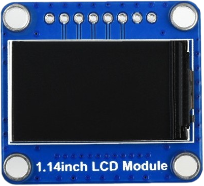
The 1.14inch LCD Module, manufactured by Waveshare (Part ID: etc), is a compact liquid crystal display designed for use in embedded systems and portable devices. With a diagonal size of 1.14 inches, this module is ideal for displaying text, graphics, and simple animations. It features low power consumption and supports communication via SPI (Serial Peripheral Interface), making it suitable for integration with microcontrollers such as Arduino, Raspberry Pi, and other development platforms.
Explore Projects Built with 1.14inch LCD Module
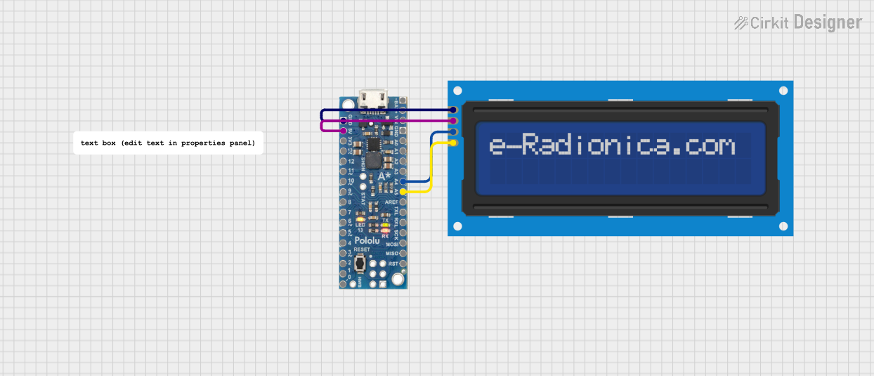


Explore Projects Built with 1.14inch LCD Module
Common Applications and Use Cases
- Wearable devices and smart gadgets
- Portable measurement instruments
- IoT (Internet of Things) devices
- Home automation systems
- Educational and hobbyist projects
Technical Specifications
Below are the key technical details of the 1.14inch LCD Module:
| Parameter | Value |
|---|---|
| Display Type | TFT LCD |
| Screen Size | 1.14 inches (diagonal) |
| Resolution | 135 x 240 pixels |
| Interface | SPI |
| Operating Voltage | 3.3V |
| Logic Voltage | 3.3V |
| Power Consumption | Low |
| Driver IC | ST7789 |
| Viewing Angle | Wide |
| Backlight | LED |
| Dimensions | Compact and lightweight |
Pin Configuration and Descriptions
The module has a set of pins for communication and power. Below is the pinout:
| Pin Name | Description |
|---|---|
| VCC | Power supply (3.3V) |
| GND | Ground |
| SCL | Serial Clock Line (SPI clock input) |
| SDA | Serial Data Line (SPI data input) |
| RES | Reset pin (active low) |
| DC | Data/Command control pin |
| BL | Backlight control (active high) |
| CS | Chip Select (active low) |
Usage Instructions
How to Use the 1.14inch LCD Module in a Circuit
- Power Supply: Connect the VCC pin to a 3.3V power source and the GND pin to ground.
- SPI Communication: Connect the SCL (clock) and SDA (data) pins to the corresponding SPI pins on your microcontroller.
- Control Pins:
- Connect the RES pin to a GPIO pin on your microcontroller for resetting the display.
- Use the DC pin to toggle between data and command modes.
- Connect the CS pin to a GPIO pin to enable or disable the module.
- Backlight: The BL pin can be connected to a GPIO pin or directly to 3.3V to control the backlight.
Important Considerations and Best Practices
- Voltage Levels: Ensure that the module operates at 3.3V logic levels. If your microcontroller uses 5V logic, use a level shifter to avoid damaging the module.
- SPI Speed: Configure the SPI clock speed according to the module's specifications to ensure reliable communication.
- Initialization: Properly initialize the display using the ST7789 driver commands before sending data.
- Backlight Control: To save power, turn off the backlight when the display is not in use.
Example Code for Arduino UNO
Below is an example of how to use the 1.14inch LCD Module with an Arduino UNO. Note that a level shifter is required for 5V to 3.3V conversion.
#include <Adafruit_GFX.h>    // Graphics library
#include <Adafruit_ST7789.h> // ST7789 driver library
#include <SPI.h>

// Define pins for the LCD module
#define TFT_CS    10  // Chip Select pin
#define TFT_RST   9   // Reset pin
#define TFT_DC    8   // Data/Command pin

// Create an instance of the display
Adafruit_ST7789 tft = Adafruit_ST7789(TFT_CS, TFT_DC, TFT_RST);

void setup() {
  // Initialize serial communication for debugging
  Serial.begin(9600);
  Serial.println("1.14inch LCD Module Test");

  // Initialize the display
  tft.init(135, 240); // Initialize with resolution 135x240
  tft.setRotation(1); // Set display orientation

  // Fill the screen with a color
  tft.fillScreen(ST77XX_BLACK);

  // Display text
  tft.setTextColor(ST77XX_WHITE);
  tft.setTextSize(2);
  tft.setCursor(10, 10);
  tft.println("Hello, World!");
}

void loop() {
  // Add your code here to update the display
}
Troubleshooting and FAQs
Common Issues and Solutions
No Display Output:
- Verify all connections, especially the SPI pins.
- Ensure the module is powered with 3.3V and not 5V.
- Check the initialization code for proper configuration.
Flickering or Unstable Display:
- Reduce the SPI clock speed in your code.
- Ensure proper grounding between the module and the microcontroller.
Backlight Not Working:
- Confirm that the BL pin is connected to 3.3V or a GPIO pin set to HIGH.
- Check for loose connections or damaged backlight LEDs.
Incorrect Colors or Graphics:
- Verify that the display driver (ST7789) is correctly initialized.
- Ensure the data sent to the display matches the expected format.
FAQs
Q: Can I use this module with a 5V microcontroller?
A: Yes, but you must use a level shifter to convert 5V logic to 3.3V logic.
Q: What is the maximum SPI clock speed supported?
A: Refer to the ST7789 datasheet for the maximum SPI clock speed. Typically, it supports up to 15-20 MHz.
Q: Can I control the backlight brightness?
A: Yes, you can use PWM (Pulse Width Modulation) on the BL pin to adjust the brightness.
Q: Is this module compatible with Raspberry Pi?
A: Yes, it can be used with Raspberry Pi via SPI, but you may need to install the appropriate libraries and drivers.
This concludes the documentation for the 1.14inch LCD Module. For further assistance, refer to the Waveshare product manual or contact their support team.