How to Use 3 digit 7 segment: Examples, Pinouts, and Specs
Introduction
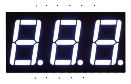
The 3-Digit 7-Segment Display (Manufacturer: ESP, Part ID: ESP32) is a versatile display component designed to show decimal numbers and some alphanumeric characters. It consists of three individual 7-segment displays, each capable of displaying digits from 0 to 9 and select characters by illuminating specific segments. This component is widely used in digital clocks, counters, timers, and other devices requiring numeric or limited alphanumeric output.
Explore Projects Built with 3 digit 7 segment
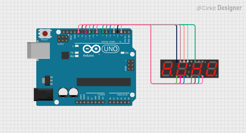
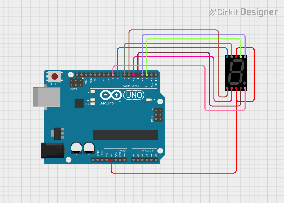
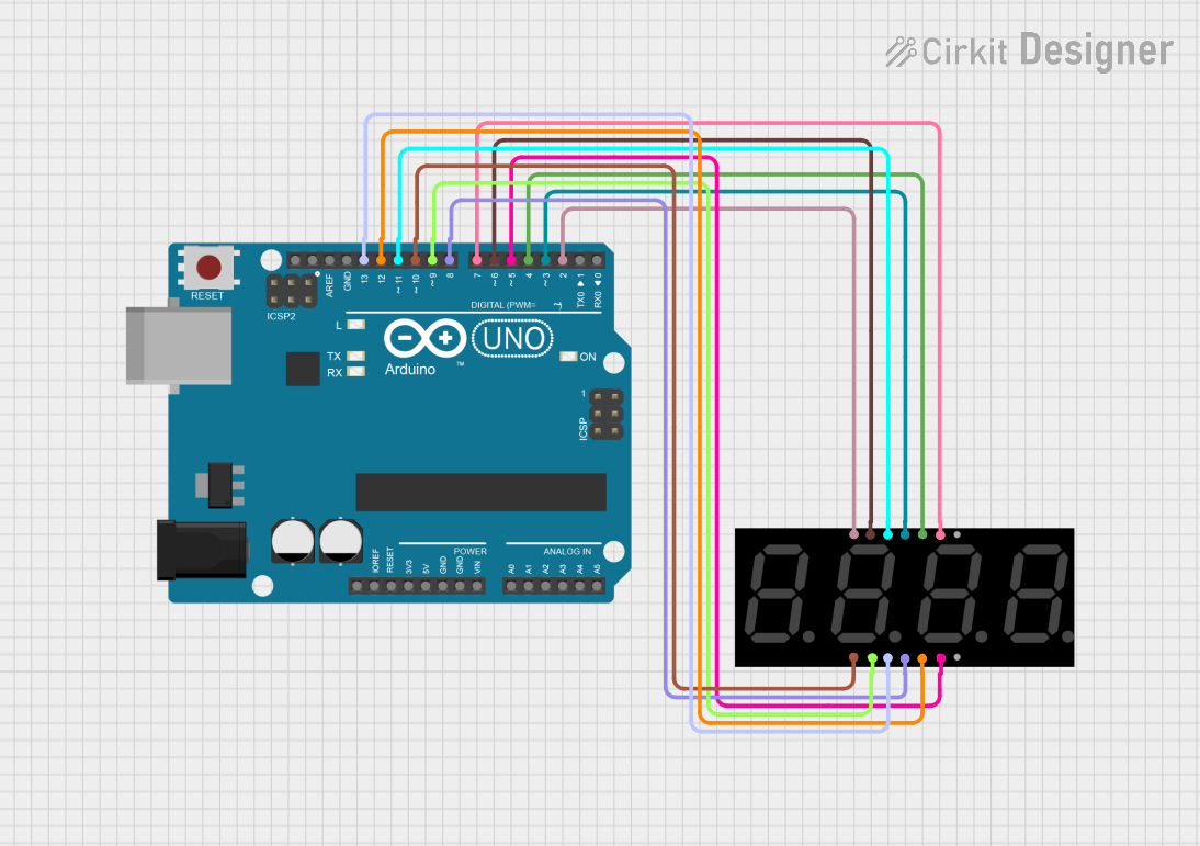
Explore Projects Built with 3 digit 7 segment
Common Applications
- Digital clocks and watches
- Electronic counters
- Timers and stopwatches
- Temperature and voltage displays
- Simple user interfaces for embedded systems
Technical Specifications
The following table outlines the key technical details of the 3-Digit 7-Segment Display:
| Parameter | Value |
|---|---|
| Manufacturer | ESP |
| Part ID | ESP32 |
| Operating Voltage | 3.3V to 5V |
| Forward Current (per segment) | 10-20 mA |
| Maximum Power Dissipation | 500 mW |
| Display Type | Common Cathode or Common Anode |
| Number of Digits | 3 |
| Segment Count | 7 segments + 1 decimal point per digit |
| Dimensions | Varies by model (e.g., 30mm x 10mm) |
Pin Configuration
The 3-Digit 7-Segment Display typically has 12 or more pins, depending on the specific model. Below is a general pinout for a common cathode configuration:
| Pin Number | Function | Description |
|---|---|---|
| 1 | Segment A | Controls the "A" segment of all digits |
| 2 | Segment B | Controls the "B" segment of all digits |
| 3 | Segment C | Controls the "C" segment of all digits |
| 4 | Digit 1 Cathode | Common cathode for the first digit |
| 5 | Segment D | Controls the "D" segment of all digits |
| 6 | Segment E | Controls the "E" segment of all digits |
| 7 | Segment F | Controls the "F" segment of all digits |
| 8 | Segment G | Controls the "G" segment of all digits |
| 9 | Decimal Point (DP) | Controls the decimal point for all digits |
| 10 | Digit 2 Cathode | Common cathode for the second digit |
| 11 | Digit 3 Cathode | Common cathode for the third digit |
| 12 | Ground (GND) | Ground connection (if applicable) |
Note: For common anode displays, the cathode pins are replaced with anode pins, and the logic is inverted.
Usage Instructions
How to Use the Component in a Circuit
- Determine the Configuration: Identify whether the display is common cathode or common anode. This will affect how you connect it to your circuit.
- Connect the Pins:
- For a common cathode display, connect the cathode pins (e.g., Digit 1, Digit 2, Digit 3) to ground.
- For a common anode display, connect the anode pins to the positive voltage supply.
- Use Current-Limiting Resistors: To prevent damage to the LEDs, connect a resistor (typically 220Ω to 1kΩ) in series with each segment pin.
- Control the Segments: Use a microcontroller (e.g., Arduino UNO) or a driver IC (e.g., MAX7219) to control the segments. Activate the appropriate pins to illuminate the desired segments.
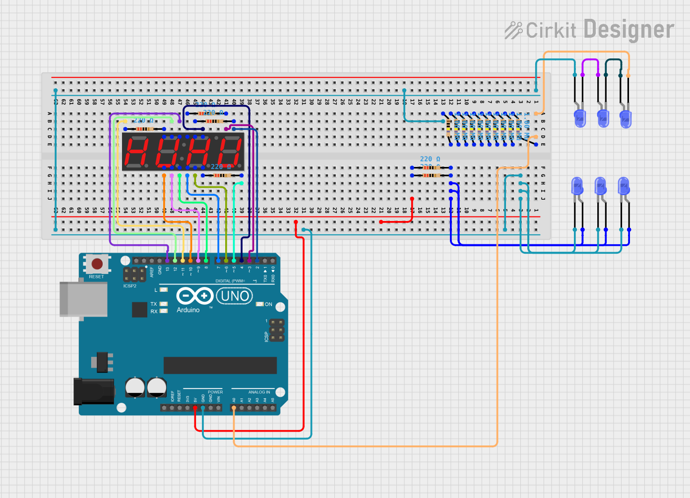
Example: Connecting to an Arduino UNO
Below is an example of how to connect and control a 3-digit 7-segment display using an Arduino UNO:
Circuit Connections
- Connect the segment pins (A, B, C, D, E, F, G, DP) to Arduino digital pins (e.g., D2 to D9).
- Connect the digit cathode pins to Arduino digital pins (e.g., D10, D11, D12) through NPN transistors for multiplexing.
- Use 220Ω resistors in series with each segment pin.
Arduino Code
// Define segment pins
const int segmentPins[] = {2, 3, 4, 5, 6, 7, 8, 9}; // A, B, C, D, E, F, G, DP
// Define digit pins
const int digitPins[] = {10, 11, 12}; // Digit 1, Digit 2, Digit 3

// Segment patterns for digits 0-9 (common cathode)
const byte digitPatterns[] = {
  0b00111111, // 0
  0b00000110, // 1
  0b01011011, // 2
  0b01001111, // 3
  0b01100110, // 4
  0b01101101, // 5
  0b01111101, // 6
  0b00000111, // 7
  0b01111111, // 8
  0b01101111  // 9
};

void setup() {
  // Set segment pins as outputs
  for (int i = 0; i < 8; i++) {
    pinMode(segmentPins[i], OUTPUT);
  }
  // Set digit pins as outputs
  for (int i = 0; i < 3; i++) {
    pinMode(digitPins[i], OUTPUT);
  }
}

void loop() {
  // Display the number "123" on the 3-digit display
  displayNumber(123);
}

void displayNumber(int number) {
  for (int digit = 0; digit < 3; digit++) {
    int digitValue = (number / (int)pow(10, digit)) % 10; // Extract digit
    setSegments(digitPatterns[digitValue]); // Set segments for the digit
    digitalWrite(digitPins[digit], LOW); // Activate the digit
    delay(5); // Short delay for multiplexing
    digitalWrite(digitPins[digit], HIGH); // Deactivate the digit
  }
}

void setSegments(byte pattern) {
  for (int i = 0; i < 8; i++) {
    digitalWrite(segmentPins[i], (pattern >> i) & 0x01); // Set each segment
  }
}
Important Considerations
- Multiplexing: To reduce the number of required pins, multiplexing is commonly used. This involves activating one digit at a time in rapid succession.
- Power Supply: Ensure the power supply can handle the total current draw of all illuminated segments.
- Brightness Control: Use pulse-width modulation (PWM) to adjust the brightness of the display.
Troubleshooting and FAQs
Common Issues
Segments Not Lighting Up:
- Check the wiring and ensure all connections are secure.
- Verify that the current-limiting resistors are correctly installed.
- Ensure the microcontroller pins are configured as outputs.
Incorrect Digits Displayed:
- Double-check the segment patterns in your code.
- Verify that the digit pins are being activated in the correct sequence.
Dim or Uneven Brightness:
- Ensure the power supply is adequate for the display's current requirements.
- Check for loose or high-resistance connections.
FAQs
Q: Can I use this display with a 3.3V microcontroller?
A: Yes, but ensure the forward voltage of the LEDs is compatible with 3.3V. You may need to adjust the resistor values accordingly.
Q: How do I display letters on the 7-segment display?
A: Some letters (e.g., A, b, C, d, E, F) can be displayed by illuminating specific segments. However, not all letters can be represented.
Q: Can I control this display without a microcontroller?
A: Yes, you can use a driver IC like the MAX7219 or 74HC595 shift register to simplify control.
By following this documentation, you can effectively integrate the 3-Digit 7-Segment Display into your projects!