
How to Use XFW-HX711-RATE: Examples, Pinouts, and Specs
 Design with XFW-HX711-RATE in Cirkit Designer
Introduction
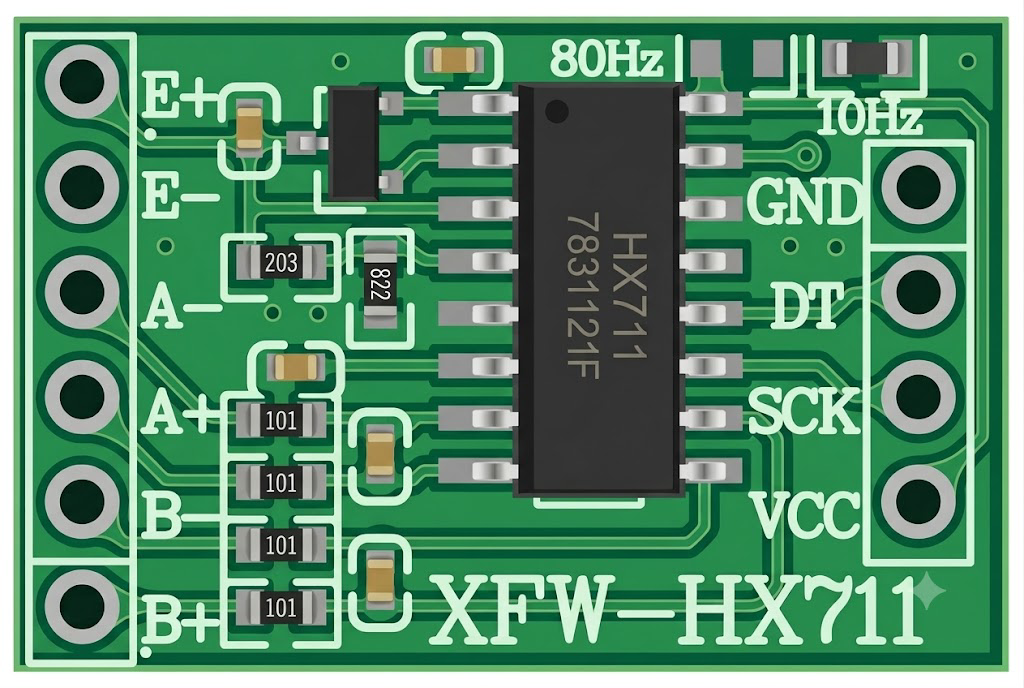
The XFW-HX711-RATE is a precision 24-bit analog-to-digital converter (ADC) manufactured by Generic. It is specifically designed for weigh scales and industrial control applications. This component is widely used in load cell systems due to its low-noise and high-precision measurement capabilities. The XFW-HX711-RATE simplifies the process of interfacing with load cells by integrating a high-resolution ADC and a programmable gain amplifier (PGA).
Explore Projects Built with XFW-HX711-RATE
 Open Project in Cirkit Designer
 Open Project in Cirkit Designer
 Open Project in Cirkit Designer
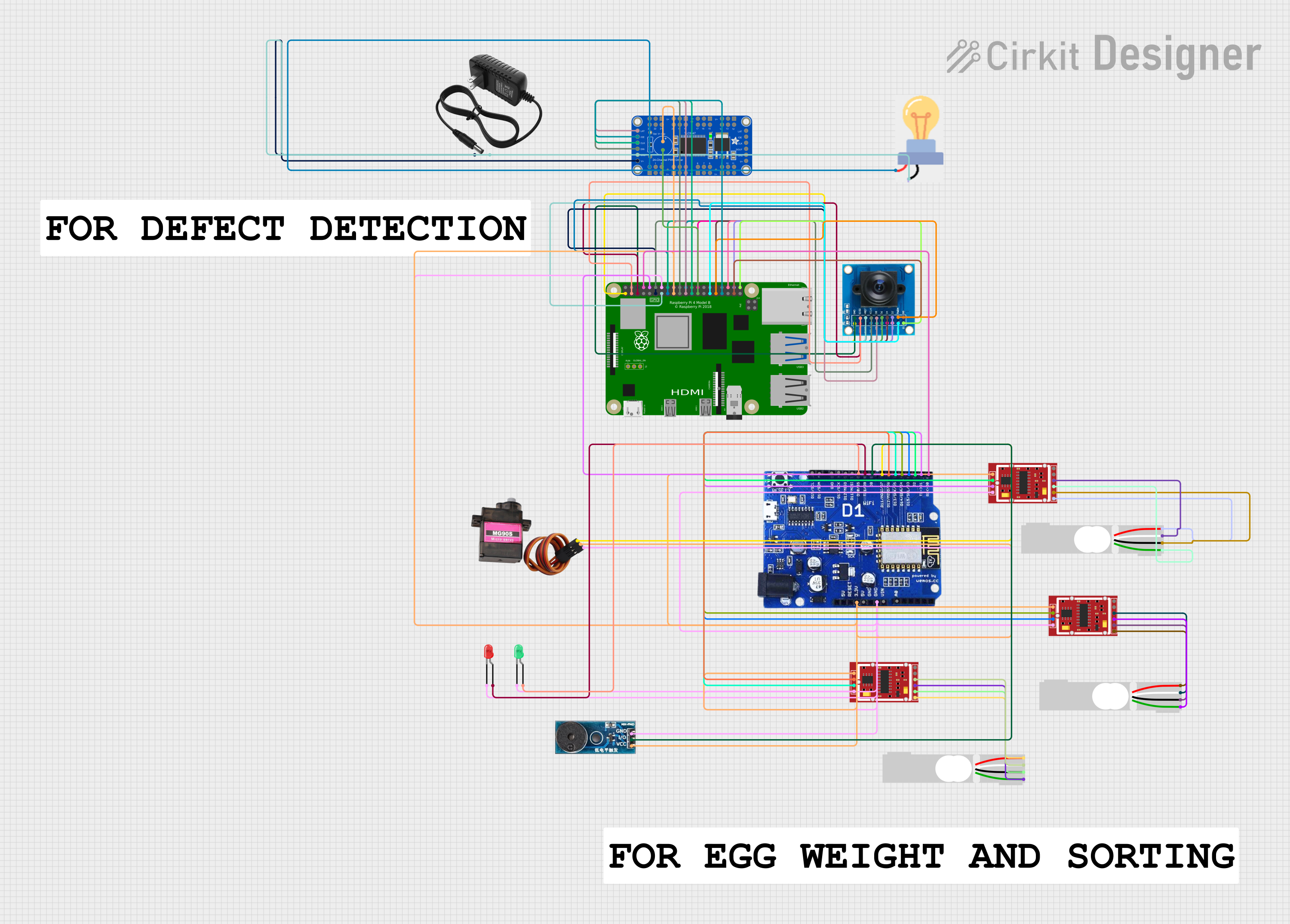 Open Project in Cirkit Designer
Explore Projects Built with XFW-HX711-RATE
Open Project in Cirkit DesignerOpen Project in Cirkit DesignerOpen Project in Cirkit DesignerOpen Project in Cirkit DesignerCommon Applications
- Digital weigh scales
- Industrial process control systems
- Load cell-based force measurement
- Pressure sensing systems
- IoT-based weight monitoring solutions
Technical Specifications
Key Technical Details
| Parameter | Value |
|---|---|
| Resolution | 24-bit |
| Operating Voltage | 2.6V to 5.5V |
| Operating Current | ~1.5mA (typical) |
| Standby Current | <1µA |
| Input Channels | 2 differential input channels |
| Programmable Gain | 32, 64, 128 |
| Data Rate | 10 Hz or 80 Hz |
| Communication Interface | Serial (2-wire interface: Clock, Data) |
| Operating Temperature Range | -40°C to +85°C |
Pin Configuration and Descriptions
The XFW-HX711-RATE comes in a 16-pin SOP package. Below is the pinout and description:
| Pin No. | Pin Name | Description |
|---|---|---|
| 1 | VCC | Power supply input (2.6V to 5.5V). |
| 2 | AVDD | Analog power supply input. Connect to VCC for most applications. |
| 3 | AGND | Analog ground. Connect to system ground. |
| 4 | BGND | Bridge ground. Connect to the ground of the load cell. |
| 5 | B+ | Positive input for the load cell bridge. |
| 6 | B- | Negative input for the load cell bridge. |
| 7 | A+ | Positive input for the second differential channel. |
| 8 | A- | Negative input for the second differential channel. |
| 9 | RATE | Data rate selection pin (Low = 10 Hz, High = 80 Hz). |
| 10 | PD_SCK | Power-down and serial clock input. |
| 11 | DOUT | Serial data output. |
| 12 | DGND | Digital ground. Connect to system ground. |
| 13-16 | NC | No connection. Leave these pins unconnected. |
Usage Instructions
How to Use the XFW-HX711-RATE in a Circuit
- Power Supply: Connect the VCC pin to a stable power source (2.6V to 5.5V). Ensure that AVDD is also connected to the same voltage as VCC.
- Load Cell Connection:
- Connect the load cell's positive and negative excitation wires to B+ and B-, respectively.
- Connect the load cell's signal wires to A+ and A- for Channel A or B+ and B- for Channel B.
- Grounding: Ensure all ground pins (AGND, BGND, DGND) are connected to a common ground.
- Data Rate Selection: Use the RATE pin to select the desired data rate:
- Connect RATE to ground for 10 Hz.
- Connect RATE to VCC for 80 Hz.
- Microcontroller Interface: Connect the PD_SCK and DOUT pins to the microcontroller's GPIO pins for communication.
Important Considerations
- Use decoupling capacitors (e.g., 0.1µF and 10µF) between VCC and ground to reduce noise.
- Keep the load cell wires as short as possible to minimize signal degradation.
- Avoid placing the XFW-HX711-RATE near high-frequency or high-power components to reduce interference.
- Ensure proper calibration of the load cell for accurate measurements.
Example: Connecting to an Arduino UNO
Below is an example of how to interface the XFW-HX711-RATE with an Arduino UNO for a basic weigh scale application.
Circuit Connections
| XFW-HX711 Pin | Arduino Pin |
|---|---|
| VCC | 5V |
| AGND | GND |
| PD_SCK | D3 |
| DOUT | D2 |
Arduino Code
#include "HX711.h" // Include the HX711 library

// Define pins for HX711
#define DOUT 2  // Data output pin
#define SCK 3   // Serial clock pin

HX711 scale; // Create an instance of the HX711 class

void setup() {
  Serial.begin(9600); // Initialize serial communication
  scale.begin(DOUT, SCK); // Initialize the HX711 with the defined pins
  scale.set_scale(); // Set the scale factor (calibrate as needed)
  scale.tare(); // Reset the scale to zero
  Serial.println("HX711 initialized. Place weight on the scale.");
}

void loop() {
  // Read and print the weight value
  Serial.print("Weight: ");
  Serial.print(scale.get_units(), 2); // Get weight in units (default is grams)
  Serial.println(" g");
  delay(500); // Delay for readability
}
Notes on Calibration
- Use the
scale.set_scale()function to set the calibration factor for your specific load cell. - Perform a tare operation (
scale.tare()) to zero the scale before taking measurements.
Troubleshooting and FAQs
Common Issues and Solutions
No Output or Incorrect Readings
- Ensure all connections are secure and correct.
- Verify that the load cell wires are connected to the correct pins (A+/A- or B+/B-).
- Check the power supply voltage (2.6V to 5.5V).
Fluctuating or Noisy Measurements
- Add decoupling capacitors between VCC and ground.
- Use shielded cables for the load cell connections.
- Ensure the load cell is not exposed to vibrations or environmental noise.
Microcontroller Not Receiving Data
- Verify the PD_SCK and DOUT connections to the microcontroller.
- Ensure the microcontroller's GPIO pins are configured correctly in the code.
FAQs
Q: Can I use the XFW-HX711-RATE with a 3.3V microcontroller?
A: Yes, the XFW-HX711-RATE operates within a voltage range of 2.6V to 5.5V, making it compatible with both 3.3V and 5V systems.
Q: How do I select between Channel A and Channel B?
A: Channel selection is done programmatically by sending specific commands via the PD_SCK pin. Refer to the HX711 datasheet for details.
Q: What is the maximum weight the XFW-HX711-RATE can measure?
A: The maximum weight depends on the load cell used. The XFW-HX711-RATE itself does not impose a weight limit but provides high-resolution ADC readings for the connected load cell.
Q: Can I use both channels (A and B) simultaneously?
A: No, the XFW-HX711-RATE can only read one channel at a time. You can switch between channels programmatically.
This concludes the documentation for the XFW-HX711-RATE. For further assistance, refer to the manufacturer's datasheet or contact technical support.